Lexus NX: Removal
REMOVAL
PROCEDURE
1. REMOVE FRONT SUSPENSION CROSSMEMBER SUB-ASSEMBLY
Click here .gif)
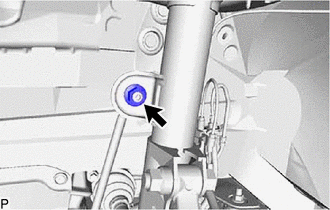
2. REMOVE FRONT STABILIZER LINK ASSEMBLY LH
| (a) Remove the nut and front stabilizer link assembly LH. HINT: If the ball joint turns together with the nut, use a 6 mm hexagon wrench to hold the stud bolt. |
|
3. REMOVE FRONT STABILIZER LINK ASSEMBLY RH
HINT:
Use the same procedure described for the LH side.
4. REMOVE FRONT SUSPENSION MEMBER BRACE
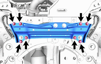
(a) Remove the 8 bolts and front suspension member brace from the front suspension crossmember sub-assembly.
5. REMOVE FRONT LOWER NO. 1 SUSPENSION ARM SUB-ASSEMBLY LH
Click here
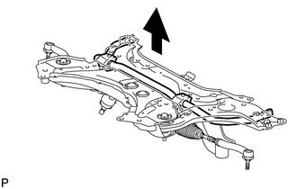
6. REMOVE FRONT STABILIZER BAR
| (a) Remove the front stabilizer bar from the front suspension crossmember sub-assembly. |
|
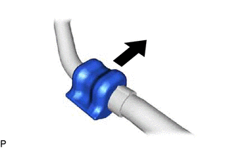
7. REMOVE FRONT STABILIZER BAR BUSHING LH
| (a) Remove the front stabilizer bar bushing from the front stabilizer bar. |
|
8. REMOVE FRONT STABILIZER BAR BUSHING RH
HINT:
Use the same procedure described for the LH side.
READ NEXT:
 Inspection
INSPECTION PROCEDURE 1. INSPECT FRONT STABILIZER LINK ASSEMBLY LH (a) Inspect the turning torque of the ball joint. (1) Secure the front stabilizer link assembly in a vise using aluminum plates. (2
Installation
INSTALLATION PROCEDURE 1. INSTALL FRONT STABILIZER BAR BUSHING LH *1 Stopper Front of the Vehicle (a) Install the front stabilizer bar bushing to the front stabilizer bar as shown in t
SEE MORE:
Front Wiper Rubber
ComponentsCOMPONENTS ILLUSTRATION *1 FRONT WIPER BLADE LH *2 WIPER RUBBER LH ReplacementREPLACEMENT CAUTION / NOTICE / HINT HINT:
Use the same procedure for RHD and LHD vehicles.
The procedure listed below is for LHD vehicles.
Use the same procedure for the RH and LH si
Removal
REMOVAL PROCEDURE 1. REMOVE REAR BUMPER COVER Click here 2. REMOVE KICK DOOR CONTROL BRACKET (a) Disconnect the connector and detach the 2 wire harness clamps. NOTICE: Do not touch the terminal of the kick door control sensor connector. (b) Remove the screw. (c) Remov
