-
Communication stop for "Panoramic View Monitor / Circumference Monitoring Camera Control Module" is indicated on "Communication Bus Check".
Click here
.gif)
-
Communication system DTCs (DTCs that start with U) that are output correspond to "Parking Assist ECU Communication Stop Mode" in "DTC Combination Table".
Click here
Lexus NX: Parking Assist ECU Communication Stop Mode
Lexus NX Service Manual / Power Source & Network / Networking / Can Communication System / Parking Assist ECU Communication Stop Mode
DESCRIPTION
| Detection Item | Symptom | Trouble Area |
|---|---|---|
| Parking Assist ECU Communication Stop Mode | Any of the following conditions are met: |
|
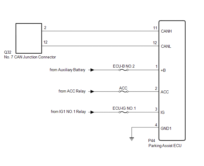
WIRING DIAGRAM
CAUTION / NOTICE / HINT
CAUTION:
When performing the confirmation driving pattern, obey all speed limits and traffic laws.
NOTICE:
- Inspect the fuses for circuits related to this system before performing the following procedure.
- Before measuring the resistance of the CAN bus, turn the power switch off and leave the vehicle for 1 minute or more without operating the key, switches or opening or closing the doors. After that, disconnect the cable from the negative (-) auxiliary battery terminal and leave the vehicle for 1 minute or more before measuring the resistance.
-
After turning the power switch off, waiting time may be required before disconnecting the cable from the negative (-) auxiliary battery terminal.
Click here
-
When disconnecting and reconnecting the auxiliary battery.
Click here
HINT:
When disconnecting and reconnecting the auxiliary battery, there is an automatic learning function that completes learning when the respective system is used.
Click here
-
Some parts must be initialized and set when replacing or removing and installing parts.
Click here
-
Because the order of diagnosis is important to allow correct diagnosis, make sure to begin troubleshooting using How to Proceed with Troubleshooting when CAN communication system related DTCs are output.
Click here
-
After performing repairs, perform the DTC check procedure and confirm that the DTCs are not output again.
DTC check procedure: Turn the power switch on (IG), wait for 1 minute or more. Then operate the suspected malfunctioning system and drive the vehicle at 60 km/h (37 mph) or more for 5 minutes or more.
-
After the repair, perform CAN Bus Check and check that all the ECUs and sensors connected to the CAN communication system are displayed as normal.
Click here
HINT:
- Operating the power switch, any switches or any doors triggers related ECU and sensor communication with the CAN, which causes resistance variation.
- Even after DTCs are cleared, if a DTC is stored again after driving the vehicle for a while, the malfunction may be occurring due to vibration of the vehicle. In such a case, wiggling the ECUs or wire harness while performing the inspection below may help determine the cause of the malfunction.
PROCEDURE
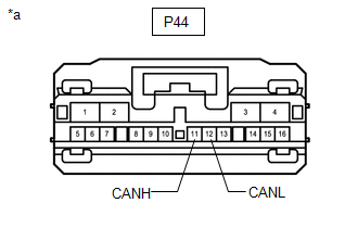
| 1. | CHECK FOR OPEN IN CAN BUS WIRE (PARKING ASSIST ECU CAN BRANCH WIRE) |
(a) Disconnect the cable from the negative (-) auxiliary battery terminal.
| (b) Disconnect the parking assist ECU connector. |
|
(c) Measure the resistance according to the value(s) in the table below.
Standard Resistance:
| Tester Connection | Condition | Specified Condition |
|---|---|---|
| P44-11 (CANH) - P44-12 (CANL) | Cable disconnected from negative (-) auxiliary battery terminal | 54 to 69 Ω |
| NG | .gif) | REPAIR OR REPLACE CAN BRANCH WIRE OR CONNECTOR |
|
.gif)
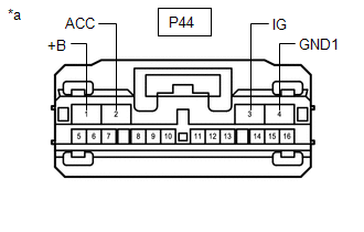
| 2. | CHECK HARNESS AND CONNECTOR (POWER SOURCE CIRCUIT) |
| (a) Measure the resistance according to the value(s) in the table below. Standard Resistance:
|
|
(b) Reconnect the cable to the negative (-) auxiliary battery terminal.
(c) Measure the voltage according to the value(s) in the table below.
Standard Voltage:
| Tester Connection | Switch Condition | Specified Condition |
|---|---|---|
| P44-1 (+B) - Body ground | Power switch off | 11 to 14 V |
| P44-2 (ACC) - Body ground | Power switch on (ACC) | 11 to 14 V |
| Power switch off | Below 1 V | |
| P44-3 (IG) - Body ground | Power switch on (IG) | 11 to 14 V |
| Power switch off | Below 1 V |
| OK | | REPLACE PARKING ASSIST ECU |
| NG | | REPAIR OR REPLACE HARNESS OR CONNECTOR (POWER SOURCE CIRCUIT) |
READ NEXT:
 Suspension Control ECU Communication Stop Mode
DESCRIPTION Detection Item Symptom Trouble Area Suspension Control ECU Communication Stop Mode Any of the following conditions are met:
Communication stop for "Suspension Control (Air
Headlight ECU Communication Stop Mode
DESCRIPTION Detection Item Symptom Trouble Area Headlight ECU Communication Stop Mode Any of the following conditions are met:
Communication stop for "Headlight swivel (AFS)" is indica
Electric Parking Brake ECU Communication Stop Mode
DESCRIPTION Detection Item Symptom Trouble Area Electric Parking Brake ECU Communication Stop Mode Any of the following conditions are met:
Communication stop for "Electric Parking Bra
SEE MORE:
Lubrication System
On-vehicle InspectionON-VEHICLE INSPECTION PROCEDURE 1. INSPECT ENGINE OIL LEVEL (a) Put the engine in inspection mode (maintenance mode). Click here (b) Warm up and stop the engine 5 minutes later, insert the engine oil level dipstick and check that the engine oil level is between the L and F ma
Data List / Active Test
DATA LIST / ACTIVE TEST DATA LIST HINT: Using the Techstream to read the Data List allows the values or states of switches, sensors, actuators and other items to be read without removing any parts. This non-intrusive inspection can be very useful because intermittent conditions or signals may be dis
© 2016-2026 Copyright www.lexunx.com
