Lexus NX: Parts Location
Lexus NX Service Manual / Engine & Hybrid System / Cruise Control / Road Sign Assist System / Parts Location
PARTS LOCATION
ILLUSTRATION
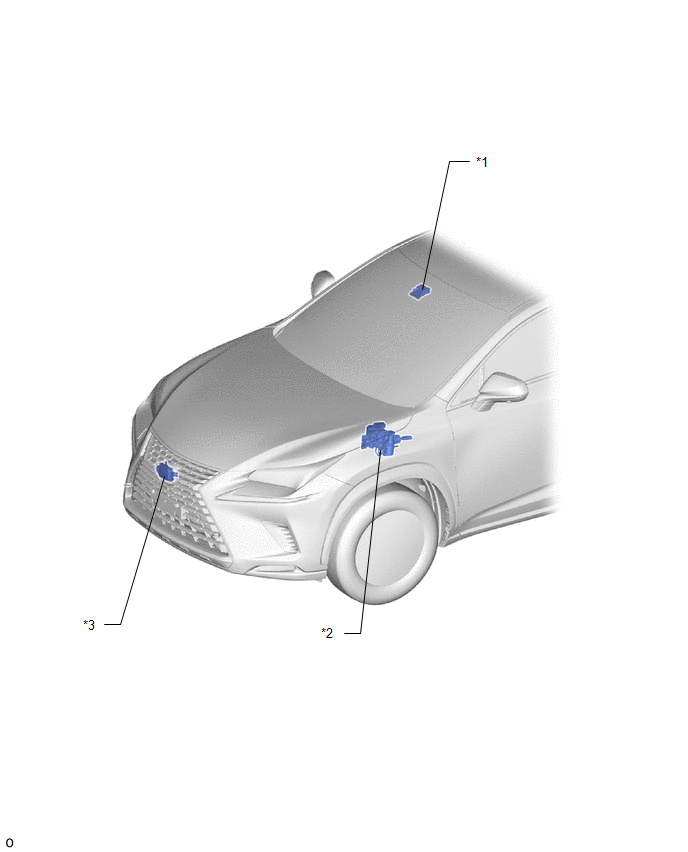
| *1 | FORWARD RECOGNITION CAMERA | *2 | BRAKE BOOSTER WITH MASTER CYLINDER ASSEMBLY - SKID CONTROL ECU |
| *3 | MILLIMETER WAVE RADAR SENSOR ASSEMBLY | - | - |
ILLUSTRATION
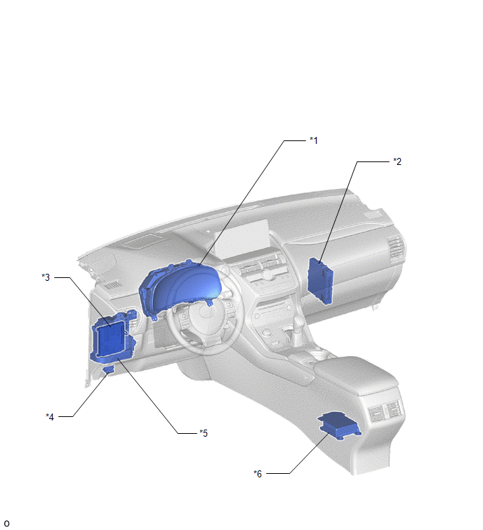
| *1 | COMBINATION METER ASSEMBLY | *2 | HYBRID VEHICLE CONTROL ECU |
| *3 | MAIN BODY ECU (MULTIPLEX NETWORK BODY ECU) | *4 | DLC3 |
| *5 | INSTRUMENT PANEL JUNCTION BLOCK ASSEMBLY - ECU-IG NO.2 FUSE | *6 | AIRBAG ECU ASSEMBLY |
READ NEXT:
 System Diagram
SYSTEM DIAGRAM
Customize Parameters
CUSTOMIZE PARAMETERS CUSTOMIZE ROAD SIGN ASSIST SYSTEM NOTICE: Be sure to make a note of the current settings before customizing. (a) Customizing with the multi-information display (1) Turn the power
Utility
UTILITY NOTICE: If the forward recognition camera has been replaced due to a malfunction in the road sign assist system, be sure to perform forward recognition camera adjustment. Otherwise all systems
SEE MORE:
Brake Warning Light Remains ON
DESCRIPTION The skid control ECU (brake booster with master cylinder assembly) is connected to the combination meter assembly via CAN communication. If any of the following is detected, the brake warning light / red (malfunction) remains on:
The skid control ECU (brake booster with master cylinde
Drive Motor "A" Inverter Voltage Sensor Circuit Low (P0D2F-266,P0D30-267)
DESCRIPTION The inverter contains a three-phase bridge circuit, which consists of 6 power transistors (IGBTs) each for the generator (MG1), motor (MG2) and rear motor (MGR). The inverter converts high-voltage direct current from the HV battery into three-phase alternating current for the generator (
© 2016-2026 Copyright www.lexunx.com
