Lexus NX: Parts Location
PARTS LOCATION
ILLUSTRATION
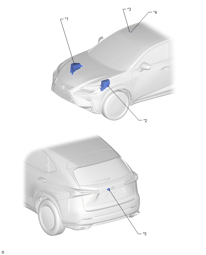
| *1 | NO. 2 ENGINE ROOM RELAY BLOCK - DCM FUSE (w/ Manual [SOS] Switch) - ECU-B NO.5 FUSE - ECU-B NO.1 FUSE | *2 | NO. 1 ENGINE ROOM RELAY BLOCK - AMP FUSE - RADIO FUSE - METER NO.1 FUSE |
| *3 | TELEPHONE MICROPHONE ASSEMBLY | *4 | ROOF HEADLINING HOLDER COVER |
| *5 | TELEVISION CAMERA ASSEMBLY | - | - |
ILLUSTRATION
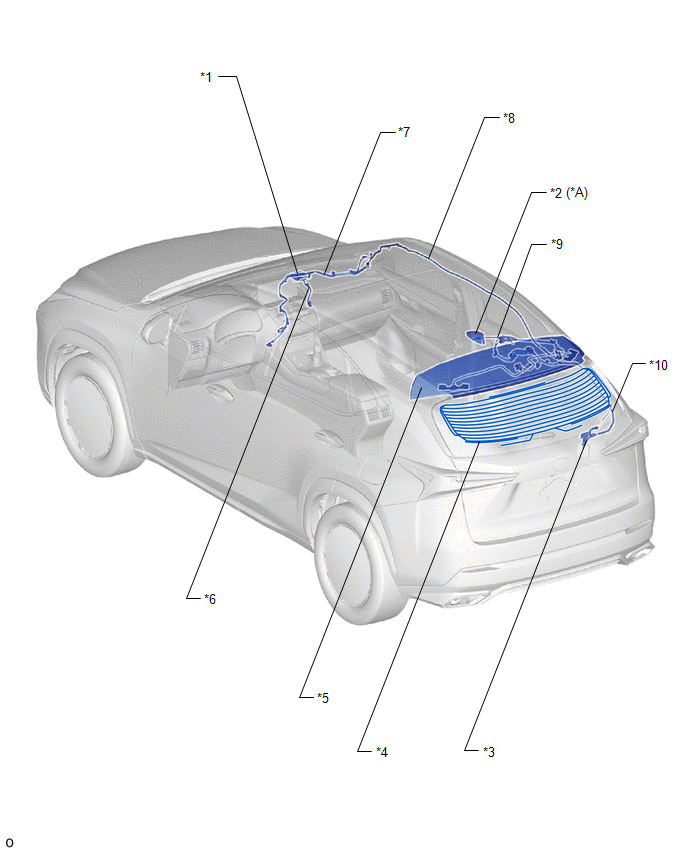
| *A | w/ SXM System or Manual (SOS) Switch | - | - |
| *1 | NAVIGATION ANTENNA ASSEMBLY | *2 | ROOF ANTENNA ASSEMBLY |
| *3 | NO. 1 AMPLIFIER ANTENNA ASSEMBLY | *4 | BACK WINDOW GLASS (WINDOW GLASS ANTENNA WIRE) |
| *5 | REAR SPOILER SUB-ASSEMBLY | *6 | ANTENNA CORD SUB-ASSEMBLY |
| *7 | NO. 1 ANTENNA CORD SUB-ASSEMBLY | *8 | NO. 2 ANTENNA CORD SUB-ASSEMBLY |
| *9 | NO. 4 ANTENNA CORD SUB-ASSEMBLY | *10 | NO. 5 ANTENNA CORD SUB-ASSEMBLY |
ILLUSTRATION
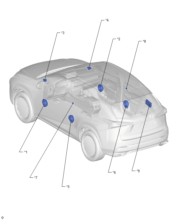
| *1 | FRONT NO. 1 SPEAKER ASSEMBLY LH | *2 | FRONT NO. 1 SPEAKER ASSEMBLY RH |
| *3 | FRONT NO. 2 SPEAKER ASSEMBLY LH | *4 | FRONT NO. 2 SPEAKER ASSEMBLY RH |
| *5 | REAR SPEAKER ASSEMBLY LH | *6 | REAR SPEAKER ASSEMBLY RH |
| *7 | REAR NO. 2 SPEAKER ASSEMBLY LH | *8 | REAR NO. 2 SPEAKER ASSEMBLY RH |
| *9 | STEREO COMPONENT AMPLIFIER ASSEMBLY | - | - |
ILLUSTRATION
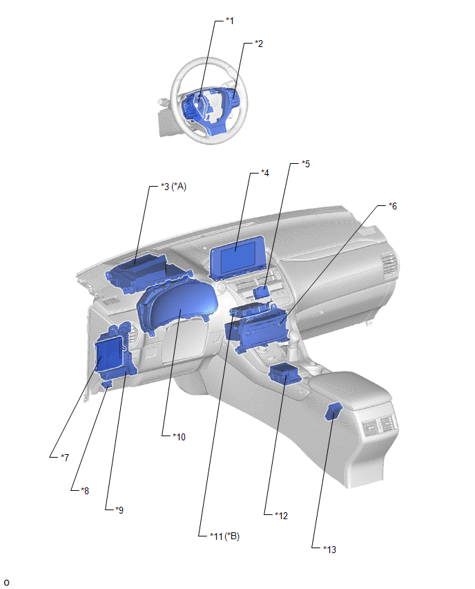
| *A | w/ Headup Display | *B | w/ Manual (SOS) Switch |
| *1 | SPIRAL CABLE SUB-ASSEMBLY | *2 | STEERING PAD SWITCH ASSEMBLY |
| *3 | COMBINATION METER MIRROR ECU | *4 | MULTI-DISPLAY ASSEMBLY |
| *5 | CLOCK ASSEMBLY | *6 | RADIO RECEIVER ASSEMBLY |
| *7 | MAIN BODY ECU (MULTIPLEX NETWORK BODY ECU) | *8 | DLC3 |
| *9 | INSTRUMENT PANEL JUNCTION BLOCK ASSEMBLY - ACC FUSE - ECU-IG NO.1 FUSE (w/ Headup Display) - ECU-IG NO.2 FUSE - IG2 NO.2 FUSE (w/ Manual [SOS] Switch) - PANEL FUSE - METER NO.2 FUSE | *10 | COMBINATION METER ASSEMBLY |
| *11 | DCM (TELEMATICS TRANSCEIVER) | *12 | REMOTE OPERATION CONTROLLER ASSEMBLY (REMOTE TOUCH) |
| *13 | NO. 1 STEREO JACK ADAPTER ASSEMBLY | - | - |
READ NEXT:
 System Diagram
SYSTEM DIAGRAM
System Description
SYSTEM DESCRIPTION DISC PLAYER OUTLINE (a) A disc player uses a laser pickup to read digital signals recorded on a disc. By converting the digital signals to analog, it can play music, video and audio
How To Proceed With Troubleshooting
CAUTION / NOTICE / HINT HINT:
Use the following procedure to troubleshoot the audio and visual system.
*: Use the Techstream.
PROCEDURE 1. VEHICLE BROUGHT TO WORKSHOP
NEXT
SEE MORE:
Headlight Dimmer Switch Circuit
DESCRIPTION The main body ECU (multiplex network body ECU) receives light control switch signals, dimmer switch signals, fog light switch signals from the headlight dimmer switch. WIRING DIAGRAM CAUTION / NOTICE / HINT NOTICE:
Recognition code registration is necessary when replacing the main bo
IG Power Source Circuit
DESCRIPTION When the power switch is turned on (IG), the IG power source circuit supplies positive (+) voltage to the multiplex tilt and telescopic ECU. The multiplex tilt and telescopic ECU also receives power switch signals via this circuit. WIRING DIAGRAM CAUTION / NOTICE / HINT NOTICE: Inspect
