Lexus NX: IG Power Source Circuit
DESCRIPTION
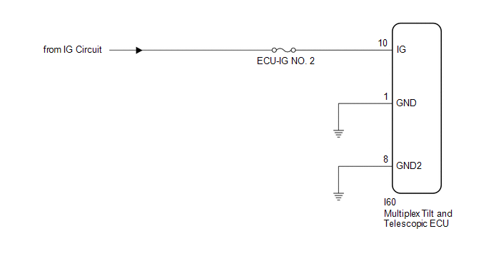
When the power switch is turned on (IG), the IG power source circuit supplies positive (+) voltage to the multiplex tilt and telescopic ECU.
The multiplex tilt and telescopic ECU also receives power switch signals via this circuit.
WIRING DIAGRAM
CAUTION / NOTICE / HINT
NOTICE:
Inspect the fuses for circuits related to this system before performing the following procedure.
PROCEDURE
| 1. | CHECK HARNESS AND CONNECTOR (MULTIPLEX TILT AND TELESCOPIC ECU - AUXILIARY BATTERY) |
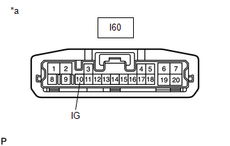
| (a) Disconnect the I60 multiplex tilt and telescopic ECU connector. |
|
(b) Measure the voltage according to the value(s) in the table below.
Standard Voltage:
| Tester Connection | Condition | Specified Condition |
|---|---|---|
| I60-10 (IG) - Body ground | Power switch on (IG) | 11 to 14 V |
| NG | .gif) | REPAIR OR REPLACE HARNESS OR CONNECTOR |
|
.gif)
| 2. | CHECK HARNESS AND CONNECTOR (MULTIPLEX TILT AND TELESCOPIC ECU - BODY GROUND) |
| (a) Disconnect the I60 multiplex tilt and telescopic ECU connector. |
|
.png)
(b) Measure the resistance according to the value(s) in the table below.
Standard Resistance:
| Tester Connection | Condition | Specified Condition |
|---|---|---|
| I60-1 (GND) - Body ground | Always | Below 1 Ω |
| I60-8 (GND2) - Body ground | Always | Below 1 Ω |
| OK | | PROCEED TO NEXT SUSPECTED AREA SHOWN IN PROBLEM SYMPTOMS TABLE |
| NG | | REPAIR OR REPLACE HARNESS OR CONNECTOR |
READ NEXT:
 Components
COMPONENTS ILLUSTRATION *1 COLUMN HOLE COVER SILENCER SHEET *2 COMBINATION SWITCH ASSEMBLY WITH SPIRAL CABLE SUB-ASSEMBLY *3 ELECTRIC POWER STEERING COLUMN SUB-ASSEMBLY *4 LOWER ST
Removal
REMOVAL CAUTION / NOTICE / HINT NOTICE:
Do not replace the spiral with sensor cable sub-assembly with the battery connected and the engine switch on (IG).
Do not rotate the spiral with sensor cab
SEE MORE:
Installation
INSTALLATION CAUTION / NOTICE / HINT NOTICE:
When the brake pedal is first depressed after replacing the brake pads or pushing back the disc brake piston, DTC C1214 may be output. As there is no malfunction, clear the DTC.
While the auxiliary battery is connected, even if the power switch is of
Lost Communication with Front Panel LIN (B14B2)
DESCRIPTION The air conditioning control assembly communicates with the air conditioning amplifier assembly through the LIN communication system. If the LIN communication system malfunctions, the air conditioning amplifier assembly does not operate even if the air conditioning control assembly is op
