Lexus NX: Parts Location
Lexus NX Service Manual / Audio & Visual & Telematics / Telematics / Telematics System / Parts Location
PARTS LOCATION
ILLUSTRATION
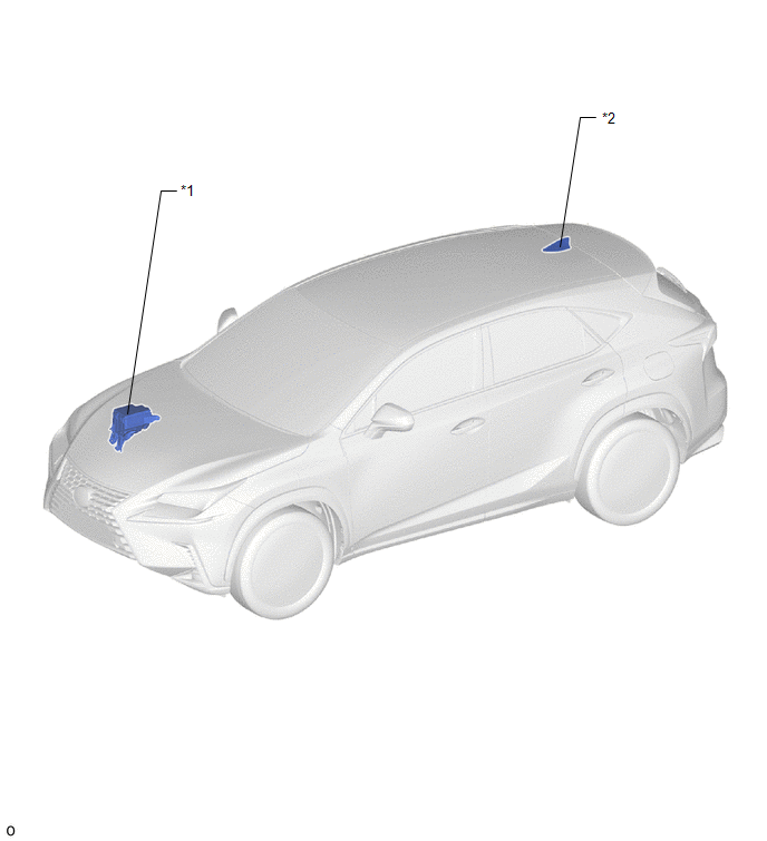
| *1 | NO. 2 ENGINE ROOM RELAY BLOCK - DCM FUSE | *2 | TELEPHONE AND GPS ANTENNA (ROOF ANTENNA ASSEMBLY) |
ILLUSTRATION
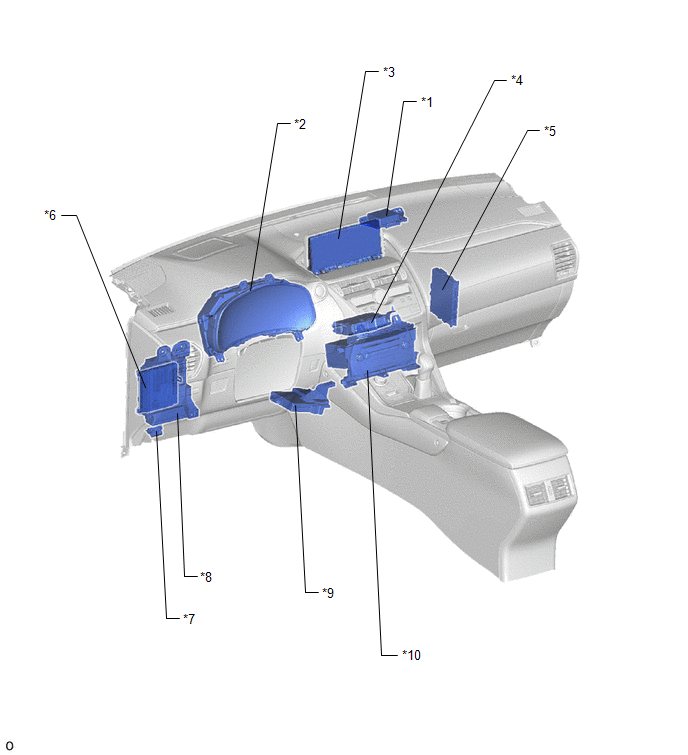
| *1 | TELEPHONE ANTENNA (NAVIGATION ANTENNA ASSEMBLY) | *2 | COMBINATION METER ASSEMBLY |
| *3 | MULTI-DISPLAY ASSEMBLY | *4 | DCM (TELEMATICS TRANSCEIVER) |
| *5 | CERTIFICATION ECU (SMART KEY ECU ASSEMBLY) | *6 | MAIN BODY ECU (MULTIPLEX NETWORK BODY ECU) |
| *7 | DLC3 | *8 | INSTRUMENT PANEL JUNCTION BLOCK ASSEMBLY - IG2 NO.2 FUSE |
| *9 | AIR CONDITIONING AMPLIFIER ASSEMBLY | *10 | RADIO RECEIVER ASSEMBLY |
READ NEXT:
 System Diagram
SYSTEM DIAGRAM
System Description
SYSTEM DESCRIPTION OUTLINE (Lexus Enform Remote) (a) Lexus Enform Remote enables the user to check the vehicle status and operate the vehicle from a remote location. (b) Lexus Enform Remote is availab
How To Proceed With Troubleshooting
CAUTION / NOTICE / HINT HINT:
Use the following procedure to troubleshoot the telematics system.
*: Use the Techstream.
PROCEDURE 1. VEHICLE BROUGHT TO WORKSHOP
NEXT
SEE MORE:
On-vehicle Inspection
ON-VEHICLE INSPECTION PROCEDURE 1. INSPECT HOOD SUB-ASSEMBLY (a) Check that the clearance measurements of areas A to E are within the standard ranges. Standard Clearance: Area Specified Condition Area Specified Condition A 2.45 to 6.45 mm (0.0965 to 0.2539 in.) B 3.7 to 6.7 mm (
Mass Air Flow Circuit Range / Performance Problem (P0101)
DESCRIPTION Refer to DTC P0102. Click here DTC No. Detection Item DTC Detection Condition Trouble Area MIL Memory P0101 Mass Air Flow Circuit Range / Performance Problem All of the following conditions continue for more than 10 seconds (2 trip detection logic): (a) The engine
© 2016-2026 Copyright www.lexunx.com
