Lexus NX: Clearance Warning ECU Power Source Circuit
DESCRIPTION
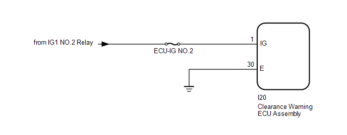
This circuit provides power to operate the clearance warning ECU assembly.
WIRING DIAGRAM
CAUTION / NOTICE / HINT
NOTICE:
Inspect the fuses for circuits related to this system before performing the following procedure.
PROCEDURE
| 1. | CHECK HARNESS AND CONNECTOR (CLEARANCE WARNING ECU ASSEMBLY POWER SOURCE) |
(a) Disconnect the I20 clearance warning ECU assembly connector.
(b) Measure the voltage according to the value(s) in the table below.
Standard Voltage:
| Tester Connection | Switch Condition | Specified Condition |
|---|---|---|
| I20-1 (IG) - Body ground | Power switch on (IG) | 11 to 14 V |
| I20-1 (IG) - Body ground | Power switch off | Below 1 V |
| NG | .gif) | REPAIR OR REPLACE HARNESS OR CONNECTOR |
|
.gif)
| 2. | CHECK HARNESS AND CONNECTOR (CLEARANCE WARNING ECU ASSEMBLY - BODY GROUND) |
(a) Disconnect the I20 clearance warning ECU assembly connector.
(b) Measure the resistance according to the value(s) in the table below.
Standard Resistance:
| Tester Connection | Condition | Specified Condition |
|---|---|---|
| I20-30 (E) - Body ground | Always | Below 1 Ω |
| OK | | PROCEED TO NEXT SUSPECTED AREA SHOWN IN PROBLEM SYMPTOMS TABLE |
.gif)
| NG | | REPAIR OR REPLACE HARNESS OR CONNECTOR |
READ NEXT:
 No. 2 Clearance Warning Buzzer Circuit
DESCRIPTION This circuit consists of the No. 2 clearance warning buzzer and clearance warning ECU assembly. An ECU-excited type buzzer is used. The ECU operates the buzzers using a sound pattern that
Sensor Frozen Indication (Dirty or Frozen)
DESCRIPTION When the ultrasonic sensor is dirty or frozen, "Parking Assist Unavailable Clean Parking Assist Sensor" is displayed on the multi-information display in the combination meter assembly. PRO
Panoramic View Monitor Switch
InspectionINSPECTION PROCEDURE 1. INSPECT NO. 2 COMBINATION SWITCH ASSEMBLY (for Type A) (a) Remove the No. 2 combination switch assembly. Click here (b) Measure the resistance according to the
SEE MORE:
Freeze Frame Data
FREEZE FRAME DATA FREEZE FRAME DATA (a) Whenever an automatic headlight beam level control system DTC is stored, the headlight ECU subassembly LH stores the current vehicle state as freeze frame data. CHECK FREEZE FRAME DATA (a) Connect the Techstream to the DLC3. (b) Turn the power switch on (IG).
Dtc Check / Clear
DTC CHECK / CLEAR CHECK DTC (CHECK USING Techstream) (a) Connect the Techstream to the DLC3. (b) Turn the power switch on (IG) and wait for 90 seconds. (c) Turn the Techstream on. (d) Enter the following menus: Body Electrical / Navigation System / Trouble Codes. Body Electrical > Navigation Syst
