- EPB NO. 1 FUSE
- EPB NO. 2 FUSE
Lexus NX: Parts Location
PARTS LOCATION
ILLUSTRATION
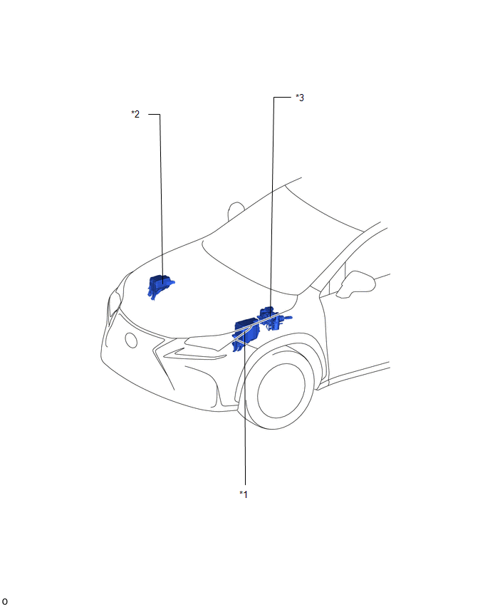
| *1 | NO. 1 ENGINE ROOM RELAY BLOCK HINT: EPB stands for Electric Parking Brake. | *2 | NO. 2 ENGINE ROOM RELAY BLOCK
|
| *3 | SKID CONTROL ECU (BRAKE BOOSTER WITH MASTER CYLINDER ASSEMBLY) | - | - |
ILLUSTRATION
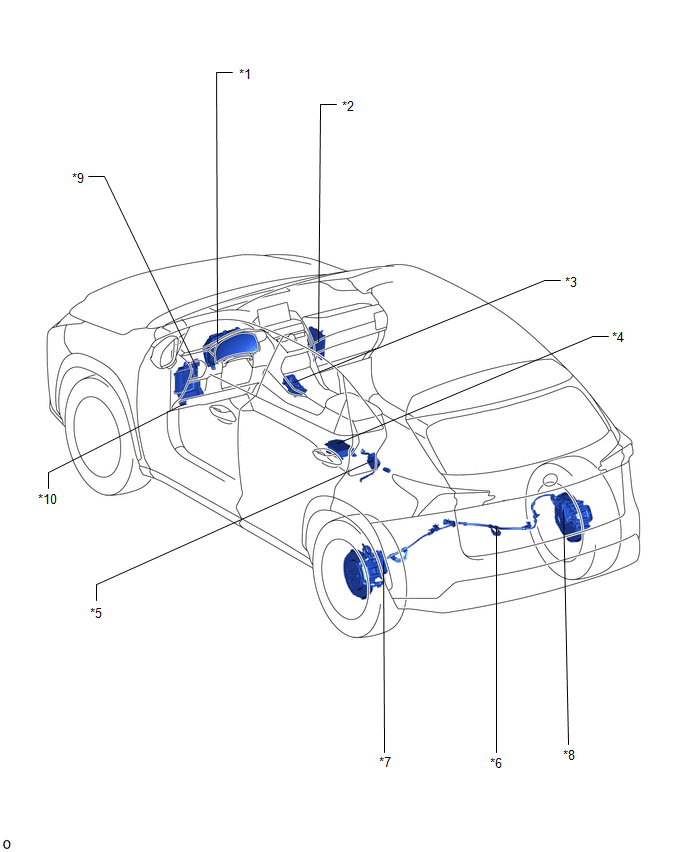
| *1 | COMBINATION METER ASSEMBLY | *2 | HYBRID VEHICLE CONTROL ECU |
| *3 | ELECTRIC PARKING BRAKE SWITCH (INTEGRATION CONTROL AND PANEL ASSEMBLY) | *4 | DECELERATION SENSOR (AIRBAG ECU ASSEMBLY) |
| *5 | PARKING BRAKE ECU ASSEMBLY | *6 | PARKING BRAKE WIRE ASSEMBLY |
| *7 | PARKING BRAKE ACTUATOR ASSEMBLY LH | *8 | PARKING BRAKE ACTUATOR ASSEMBLY RH |
| *9 | INSTRUMENT PANEL JUNCTION BLOCK ASSEMBLY
| *10 | DLC3 |
READ NEXT:
 System Diagram
SYSTEM DIAGRAM
System Description
SYSTEM DESCRIPTION SYSTEM DESCRIPTION (a) The electric parking brake system electronically controls the parking brake lock and release operations using actuators. The main functions are as follows: F
How To Proceed With Troubleshooting
CAUTION / NOTICE / HINT HINT: *: Use the Techstream. PROCEDURE 1. VEHICLE BROUGHT TO WORKSHOP
NEXT 2. CUSTOMER PROBLEM ANALYSIS (a) Interview the customer and confir
SEE MORE:
Disassembly
DISASSEMBLY PROCEDURE 1. REMOVE MILLIMETER WAVE RADAR SENSOR ASSEMBLY Click here 2. REMOVE FRONT TELEVISION CAMERA ASSEMBLY (w/ Panoramic View Monitor System) Click here 3. REMOVE FRONT CENTER ULTRASONIC SENSOR (w/ Intuitive Parking Assist System) Click here 4. REMOVE FRONT BUMPER EXTENSION
Installation
INSTALLATION CAUTION / NOTICE / HINT HINT: A bolt without a torque specification is shown in the standard bolt chart. Click here PROCEDURE 1. INSTALL LOWER INSTRUMENT PANEL SUB-ASSEMBLY (a) Cut off both ends at the positions shown in the illustration (runner) (when installing new part). *a C
© 2016-2026 Copyright www.lexunx.com
