Lexus NX: Power Back Door cannot be Opened or Closed Using the Back Door Control Switch
DESCRIPTION
When the power back door cannot be closed using the back door control switch, either of the following may be malfunctioning: 1) back door control switch circuit or 2) multiplex network door ECU.
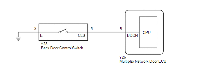
WIRING DIAGRAM
CAUTION / NOTICE / HINT
NOTICE:
If the replacement, removal and installation of the multiplex network door ECU or disconnection of the connectors of the multiplex network door ECU has been performed, initialize the power back door system.
Click here .gif)
PROCEDURE
| 1. | READ VALUE USING TECHSTREAM |
(a) Read the Data List according to the display on the Techstream.
Click here
| Tester Display | Measurement Item | Range | Normal Condition | Diagnostic Note |
|---|---|---|---|---|
| PBD Close SW | Back door control switch signal | ON or OFF | ON: Back door control switch pushed OFF: Back door control switch not pushed | - |
| Tester Display |
|---|
| PBD Close SW |
OK:
The back door control switch functions as specified in the normal condition column.
| OK | .gif) | REPLACE MULTIPLEX NETWORK DOOR ECU |
|
.gif)
| 2. | INSPECT BACK DOOR CONTROL SWITCH |
(a) Remove the back door control switch.
Click here
(b) Inspect the back door control switch.
Click here
| NG | | REPLACE BACK DOOR CONTROL SWITCH |
|
| 3. | CHECK HARNESS AND CONNECTOR (BACK DOOR CONTROL SWITCH - MULTIPLEX NETWORK DOOR ECU AND BODY GROUND) |
(a) Disconnect the Y28 back door control switch connector.
(b) Disconnect the Y26 multiplex network door ECU connector.
(c) Measure the resistance according to the value(s) in the table below.
Standard Resistance:
| Tester Connection | Condition | Specified Condition |
|---|---|---|
| Y28-5 (CLS) - Y26-8 (BDDN) | Always | Below 1 Ω |
| Y28-2 (E) - Body ground | Always | Below 1 Ω |
| Y28-5 (CLS) or Y26-8 (BDDN) - Body ground | Always | 10 kΩ or higher |
| OK | | REPLACE MULTIPLEX NETWORK DOOR ECU |
| NG | | REPAIR OR REPLACE HARNESS OR CONNECTOR |
READ NEXT:
 Power Back Door cannot be Opened Using the Back Door Opener Switch
DESCRIPTION The multiplex network door ECU receives an open signal from the back door opener switch assembly via the certification ECU (smart key ECU assembly). WIRING DIAGRAM CAUTION / NOTICE / HINT
Power Back Door Warning System does not Operate
DESCRIPTION When the power back door warning system does not operate, one of the following may be malfunctioning: 1) wireless door lock control system, 2) power back door warning buzzer circuit or 3)
Jam Protection Function Activates During Power Back Door Operation
DESCRIPTION When the jam protection function activates during power back door operation, one of the following may be the cause: 1) improper fit of back door, or a foreign object is stuck in the back d
SEE MORE:
Rear Door LH Entry Unlock Function does not Operate
DESCRIPTION If the entry unlock function does not operate for the rear door LH only, but the entry lock function operates, the request code is being transmitted properly from the rear door LH. In this case, there may be a problem related to the unlock sensor (connection between the certification ECU
Fuel Receiver Gauge Display Malfunction
DESCRIPTION OPERATION The combination meter assembly uses the fuel injection volume signal from the ECM, fuel sender gauge assembly to detect the amount of fuel remaining in the fuel tank assembly. Each gauge assembly has a variable resistor whose resistance changes according to the amount of fuel r
