Lexus NX: Jam Protection Function Activates During Power Back Door Operation
DESCRIPTION
When the jam protection function activates during power back door operation, one of the following may be the cause: 1) improper fit of back door, or a foreign object is stuck in the back door, 2) malfunctioning power back door sensor assembly circuit or 3) malfunctioning multiplex network door ECU.
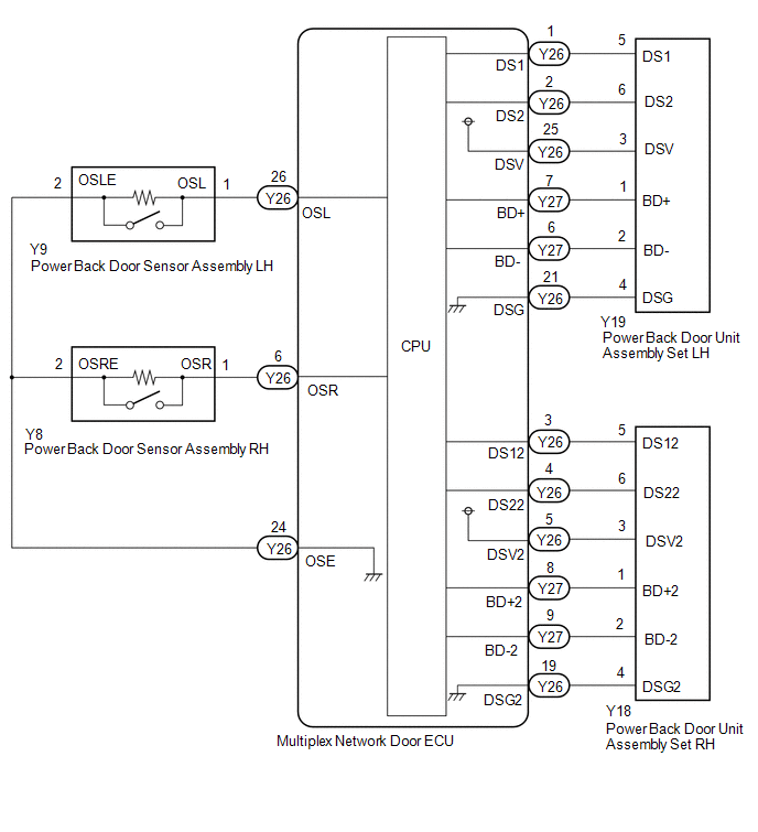
WIRING DIAGRAM
CAUTION / NOTICE / HINT
NOTICE:
If the replacement, removal and installation of the multiplex network door ECU or disconnection of the connectors of the multiplex network door ECU has been performed, initialize the power back door system.
Click here .gif)
PROCEDURE
| 1. | CHECK POWER BACK DOOR SYSTEM |
(a) Check if there are any foreign objects interfering with back door operation.
| Result | Proceed to |
|---|---|
| There are no foreign objects | A |
| There are foreign objects | B |
| B | .gif) | REMOVE FOREIGN OBJECT |
|
.gif)
| 2. | CHECK BACK DOOR OPERATION |
(a) Check back door operation.
(1) Turn the main switch so that it is not pushed.
Click here
NOTICE:
This check is possible only when the "Power Back Door Function" customization setting using the multi-information display in the combination meter assembly is set to OFF (initial setting is ON).
(2) Open/close the back door by hand.
| Result | Proceed to |
|---|---|
| The back door fully opens and closes smoothly | A |
| The back door does not fully open and close smoothly | B |
(b) Check main switch condition.
NOTICE:
The "Power Back Door Function" customization setting using the multi-information display in the combination meter assembly is set to ON (initial setting is ON).
(1) Turn the main switch so that it is pushed.
Click here
| B | | ADJUST BACK DOOR |
|
| 3. | READ VALUE USING TECHSTREAM |
(a) Check the Data List to determine if the power back door sensor assembly functions properly.
Click here
| Tester Display | Measurement Item | Range | Normal Condition | Diagnostic Note |
|---|---|---|---|---|
| PBD Touch Sensor (Right) | Power back door sensor assembly RH signal | ON, OFF or Open | ON: Power back door sensor assembly RH pressed OFF: Power back door sensor assembly RH not pressed Open: Power back door sensor assembly RH circuit open | - |
| PBD Touch Sensor (Left) | Power back door sensor assembly LH signal | ON, OFF or Open | ON: Power back door sensor assembly LH pressed OFF: Power back door sensor assembly LH not pressed Open: Power back door sensor assembly LH circuit open | - |
| Tester Display |
|---|
| PBD Touch Sensor (Right) |
| PBD Touch Sensor (Left) |
| Result | Proceed to |
|---|---|
| On the Techstream screen, ON or OFF is displayed accordingly | A |
| On the Techstream screen, ON or OFF is not displayed accordingly or Open is displayed for power back door sensor assembly RH | B |
| On the Techstream screen, ON or OFF is not displayed accordingly or Open is displayed for power back door sensor assembly LH | C |
| B | | GO TO STEP 6 |
| C | | GO TO STEP 8 |
|
| 4. | REPLACE POWER BACK DOOR UNIT ASSEMBLY SET (LH/RH) |
(a) Temporarily replace the power back door unit assembly set with a new or normally functioning one.
Click here
|
| 5. | CHECK POWER BACK DOOR SYSTEM |
(a) Check power back door system operation.
Click here
OK:
Power back door system operates normally
| OK | | END (POWER BACK DOOR UNIT ASSEMBLY SET WAS DEFECTIVE) |
| NG | | REPLACE MULTIPLEX NETWORK DOOR ECU |
| 6. | INSPECT POWER BACK DOOR SENSOR ASSEMBLY RH |
(a) Remove the power back door sensor assembly RH.
Click here
(b) Inspect the power back door sensor assembly RH.
Click here
| NG | | REPLACE POWER BACK DOOR SENSOR ASSEMBLY RH |
|
| 7. | CHECK HARNESS AND CONNECTOR (POWER BACK DOOR SENSOR ASSEMBLY RH - MULTIPLEX NETWORK DOOR ECU) |
(a) Disconnect the Y8 power back door sensor assembly RH connector.
(b) Disconnect the Y26 multiplex network door ECU connector.
(c) Measure the resistance according to the value(s) in the table below.
Standard Resistance:
| Tester Connection | Condition | Specified Condition |
|---|---|---|
| Y8-1 (OSR) - Y26-6 (OSR) | Always | Below 1 Ω |
| Y8-2 (OSRE) - Y26-24 (OSE) | Always | Below 1 Ω |
| Y8-1 (OSR) or Y26-6 (OSR) - Body ground | Always | 10 kΩ or higher |
| Y8-2 (OSRE) or Y26-24 (OSE) - Body ground | Always | 10 kΩ or higher |
| OK | | REPLACE MULTIPLEX NETWORK DOOR ECU |
| NG | | REPAIR OR REPLACE HARNESS OR CONNECTOR |
| 8. | INSPECT POWER BACK DOOR SENSOR ASSEMBLY LH |
(a) Remove the power back door sensor assembly LH.
Click here
(b) Inspect the power back door sensor assembly LH.
Click here
| NG | | REPLACE POWER BACK DOOR SENSOR ASSEMBLY LH |
|
| 9. | CHECK HARNESS AND CONNECTOR (POWER BACK DOOR SENSOR ASSEMBLY LH - MULTIPLEX NETWORK DOOR ECU) |
(a) Disconnect the Y9 power back door sensor assembly LH connector.
(b) Disconnect the Y26 multiplex network door ECU connector.
(c) Measure the resistance according to the value(s) in the table below.
Standard Resistance:
| Tester Connection | Condition | Specified Condition |
|---|---|---|
| Y9-1 (OSL) - Y26-26 (OSL) | Always | Below 1 Ω |
| Y9-2 (OSLE) - Y26-24 (OSE) | Always | Below 1 Ω |
| Y9-1 (OSL) or Y26-26 (OSL) - Body ground | Always | 10 kΩ or higher |
| Y9-2 (OSLE) or Y26-24 (OSE) - Body ground | Always | 10 kΩ or higher |
| OK | | REPLACE MULTIPLEX NETWORK DOOR ECU |
| NG | | REPAIR OR REPLACE HARNESS OR CONNECTOR |
READ NEXT:
 Power Back Door cannot be Operated Using Kick Sensor
DESCRIPTION The kick door control sensor receives vehicle speed, IG and ACC signals from the main body ECU (multiplex network body ECU) via LIN communication and uses the information to stop sensor os
Lock Function does not Operate (Close &)
DESCRIPTION The door control switch signal is sent to the multiplex network door ECU. If the power back door system does not operate when the door control switch is operated, the door control switch c
SEE MORE:
Inspection
INSPECTION PROCEDURE 1. INSPECT SERVICE PLUG GRIP (a) Measure the resistance according to the value(s) in the table below. Standard Resistance: Tester Connection Condition Specified Condition Service plug grip Always Below 1 Ω If the result is not as specified, replace the ser
CAN Communication Failure (Message Registry) (U1000)
DESCRIPTION This DTC is output when an internal malfunction of the CAN communication-related ECU is stored. DTC No. Detection Item DTC Detection Condition Trouble Area U1000 CAN Communication Failure (Message Registry) A headlight ECU sub-assembly LH CAN communication function malfu
