Lexus NX: Rear Power Window RH does not Operate with Rear Power Window Switch RH
DESCRIPTION
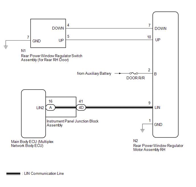
When the power switch is on (IG), the rear power window regulator motor assembly RH is operated by the rear power window regulator switch assembly (for rear RH door). The rear power window regulator motor assembly RH has motor, regulator and ECU functions.
WIRING DIAGRAM
CAUTION / NOTICE / HINT
NOTICE:
-
The power window control system uses the LIN communication system. Inspect the communication function by following How to Proceed with Troubleshooting. Troubleshoot the power window control system after confirming that the communication system is functioning properly.
Click here
.gif)
-
If the rear power window regulator motor assembly RH (for rear RH door) has been replaced with a new one, initialize the power window control system.
Click here
- Check that the window lock switch is off before performing the following procedure.
- Inspect the fuses for circuits related to this system before performing the following procedure.
- Recognition code registration is necessary when replacing the main body ECU (multiplex network body ECU).
-
If the main body ECU (multiplex network body ECU) is replaced, refer to Registration.
Click here
PROCEDURE
| 1. | READ VALUE USING TECHSTREAM (MAIN BODY) |
(a) Read the Data List according to the display on the Techstream.
Click here
| Tester Display | Measurement Item | Range | Normal Condition | Diagnostic Note |
|---|---|---|---|---|
| Communication RR-Door Motor | Connection status between power window regulator motor assembly RH (for rear RH door) and main body ECU (multiplex network body ECU) | STOP or OK | STOP: Communication stopped OK: Normal communication | - |
| Tester Display |
|---|
| Communication RR-Door Motor |
OK:
On the Techstream screen, OK is displayed.
| NG | .gif) | GO TO LIN COMMUNICATION SYSTEM |
|
.gif)
| 2. | READ VALUE USING TECHSTREAM (RR-DOOR MOTOR) |
(a) Read the Data List according to the display on the Techstream.
Click here
| Tester Display | Measurement Item | Range | Normal Condition | Diagnostic Note |
|---|---|---|---|---|
| RR Door P/W Up SW | Rear RH door power window manual up switch signal | OFF or ON | OFF: Rear RH door power window manual up switch not being operated ON: Rear RH door power window manual up switch being operated | - |
| RR Door P/W Down SW | Rear RH door power window manual down switch signal | OFF or ON | OFF: Rear RH door power window manual down switch not being operated ON: Rear RH door power window manual down switch being operated | - |
| Tester Display |
|---|
| RR Door P/W Up SW |
| RR Door P/W Down SW |
OK:
On the Techstream screen, ON or OFF is displayed accordingly.
| NG | | GO TO STEP 4 |
|
| 3. | PERFORM ACTIVE TEST USING TECHSTREAM (RR-DOOR MOTOR) |
(a) Perform the Active Test according to the display on the Techstream.
Click here
CAUTION:
Be careful to avoid injuries as this test causes vehicle parts to move. During the Active Test, the jam protection function will not operate.
Body Electrical > RR-Door Motor > Active Test| Tester Display | Measurement Item | Control Range | Diagnostic Note |
|---|---|---|---|
| Power Window | Power window | OFF / DOWN / UP | - |
| Tester Display |
|---|
| Power Window |
HINT:
Up and down movement does not occur if the arrow is not pressed and held.
OK:
Rear RH power window operates normally.
| OK | | REPLACE MAIN BODY ECU (MULTIPLEX NETWORK BODY ECU) |
| NG | | REPLACE REAR POWER WINDOW REGULATOR MOTOR ASSEMBLY RH |
| 4. | INSPECT REAR POWER WINDOW REGULATOR SWITCH ASSEMBLY (FOR REAR RH DOOR) |
(a) Remove the rear power window regulator switch assembly (for rear RH door).
Click here
(b) Inspect the rear power window regulator switch assembly (for rear RH door).
Click here
| NG | | REPLACE REAR POWER WINDOW REGULATOR SWITCH ASSEMBLY (FOR REAR RH DOOR) |
|
| 5. | CHECK HARNESS AND CONNECTOR (REAR POWER WINDOW REGULATOR SWITCH ASSEMBLY [FOR REAR RH DOOR] - REAR POWER WINDOW REGULATOR MOTOR ASSEMBLY RH AND BODY GROUND) |
(a) Disconnect the N1 power window regulator switch assembly (for rear RH door) connector.
(b) Disconnect the N2 rear power window regulator motor assembly RH connector.
(c) Measure the resistance according to the value(s) in the table below.
Standard Resistance:
| Tester Connection | Condition | Specified Condition |
|---|---|---|
| N1-5 (UP) - N2-10 (UP) | Always | Below 1 Ω |
| N1-4 (DOWN) - N2-7 (DOWN) | Always | Below 1 Ω |
| N1-7 (GND) - Body ground | Always | Below 1 Ω |
| N1-5 (UP) or N2-10 (UP) - Body ground | Always | 10 kΩ or higher |
| N1-4 (DOWN) or N2-7 (DOWN) - Body ground | Always | 10 kΩ or higher |
| OK | | REPLACE REAR POWER WINDOW REGULATOR MOTOR ASSEMBLY RH |
| NG | | REPAIR OR REPLACE HARNESS OR CONNECTOR |
READ NEXT:
 Driver Side Power Window Auto Up / Down Function does not Operate with Power Window Master Switch
DESCRIPTION If the manual up and down function operates normally but the auto up and down function does not, then fail-safe mode may be functioning. If power window initialization has not been perform
Front Passenger Side Power Window Auto Up / Down Function does not Operate with Front Passenger Side Power Window Switch
DESCRIPTION If the manual up and down function operates normally but the auto up and down function does not, then fail-safe mode may be functioning. If power window initialization has not been perform
Rear Power Window LH Auto Up / Down Function does not Operate with Rear Power Window Switch LH
DESCRIPTION If the manual up and down function operates normally but the auto up and down function does not, then fail-safe mode may be functioning. If power window initialization has not been perform
SEE MORE:
Lost Communication with ECM / PCM "A" (U0100,U0142,U023A)
DESCRIPTION
U0100: The meter mirror sub-assembly receives signals from the ECM via CAN communication.
U0142: The meter mirror sub-assembly receives signals from the main body ECU (multiplex network body ECU) via CAN communication.
U023A: The meter mirror sub-assembly receives signals from the
Installation
INSTALLATION PROCEDURE 1. INSTALL RAIN SENSOR TAPE NOTICE: The rain sensor tape is reusable. Only replace the tape if it is damaged or contaminated. (a) Clean the rain sensor sensing portion with a piece of cloth, etc. (b) Peel off the smaller release sheet, and then attach the rain sensor tape o
