Lexus NX: Removal
REMOVAL
PROCEDURE
1. REMOVE REAR SEAT ASSEMBLY
(a) for Manual Seat:
Click here .gif)
(b) for Power Seat:
Click here
2. REMOVE REAR FLOOR FINISH PLATE
Click here
3. DISCONNECT REAR DOOR OPENING TRIM WEATHERSTRIP RH
Click here
4. REMOVE UPPER DECK TRIM SIDE BOARD RH
Click here
5. REMOVE ROPE HOOK ASSEMBLY
Click here
6. REMOVE LUGGAGE HOLD BELT STRIKER ASSEMBLY
Click here
7. REMOVE NO. 1 LUGGAGE COMPARTMENT TRIM HOOK
Click here
8. REMOVE DECK TRIM SIDE PANEL ASSEMBLY RH
Click here
9. REMOVE PARKING ASSIST ECU
(a) Disconnect the 3 connectors.
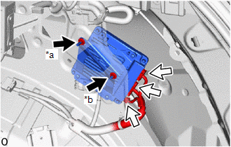
| *a | Nut A |
| *b | Nut B |
.png) | Connector |
(b) Loosen the temporary nut (A).
(c) Remove the nut (B).
(d) Lift up the parking assist ECU, detach the welding bolt on the nut (A) from the body panel hole and remove the parking assist ECU from the vehicle.
(e) Remove the nut (A).
NOTICE:
Do not reuse the removed nut (A) and nut (B).
READ NEXT:
 Installation
INSTALLATION PROCEDURE 1. INSTALL PARKING ASSIST ECU (a) Temporarily install a new nut (A) so that the nut cannot fall, but do not tighten it. *a Nut A *b Nut B Connector (b) Con
Precaution
PRECAUTION POINTS TO NOTE WHEN SERVICING (a) Pay attention to the following points when servicing. (1) When "!" mark is displayed on the multi-display assembly after disconnecting the cable from the n
SEE MORE:
Inspection
INSPECTION PROCEDURE 1. INSPECT GLOVE BOX LIGHT ASSEMBLY (a) Apply battery voltage to the connector and check the light illumination condition. OK: Measurement Condition Specified Condition Battery positive (+) → 2 (B) Battery negative (-) → 1 (L) Illuminates If the result is n
Installation
INSTALLATION PROCEDURE 1. INSTALL FRONT SEAT INNER BELT ASSEMBLY LH (a) Install the front seat belt anchor plate. (b) Install the front seat inner belt assembly LH with the nut. Torque: 42 N·m {428 kgf·cm, 31 ft·lbf} NOTICE: Do not allow the anchor part of the front seat inner belt assembly L
