Lexus NX: Removal
REMOVAL
CAUTION / NOTICE / HINT
NOTICE:
While the auxiliary battery is connected, even if the power switch is off, the brake control system activates when the brake pedal is depressed or any door courtesy switch turns on. Therefore, when servicing the brake system components, do not operate the brake pedal or open/close the doors while the auxiliary battery is connected.
PROCEDURE
1. REMOVE NO. 3 DECK BOARD SUB-ASSEMBLY
Click here .gif)
2. REMOVE REAR DECK FLOOR BOX
Click here
3. REMOVE DECK FLOOR BOX LH
Click here
4. PRECAUTION
CAUTION:
Be sure to read Precoution thoroughly before serving.
Click here
NOTICE:
After turning the power switch off, there may be a waiting time before disconnecting the negative (-) auxiliary battery terminal.
Click here
5. DISCONNECT CABLE FROM NEGATIVE AUXILIARY BATTERY TERMINAL
CAUTION:
- Wait at least 90 seconds after disconnecting the cable from the negative (-) auxiliary battery terminal to disable the SRS system.
- If the airbag deploys for any reason. it may cause a serious accident.
(a) Loosen the nut and disconnect the negative (-) auxiliary battery terminal.
6. REMOVE LOWER NO. 1 INSTRUMENT PANEL AIRBAG ASSEMBLY
Click here
7. REMOVE BRAKE PEDAL STROKE SENSOR ASSEMBLY
| (a) Disconnect the connector from the brake pedal stroke sensor assembly. |
|
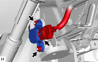
(b) Remove the 2 nuts and brake pedal stroke sensor assembly from the brake pedal support assembly.
HINT:
- Do not drop the brake pedal stroke sensor assembly.
- If the brake pedal stroke sensor assembly has been dropped, replace the brake pedal stroke sensor assembly with a new one.
READ NEXT:
 Installation
INSTALLATION CAUTION / NOTICE / HINT NOTICE: While the battery is connected, even if the power switch is off, the brake control system activates when the brake pedal is depressed or any door courtesy
Precaution
PRECAUTION TROUBLESHOOTING PRECAUTIONS (a) When there is a malfunction with terminal contact points or part installation problems, removal and installation of the suspected problem parts may return th
SEE MORE:
Dtc Check / Clear
DTC CHECK / CLEAR CHECK DTC (a) Connect the Techstream to the DLC3. (b) Turn the power switch on (IG). (c) Turn the Techstream on. (d) Enter the following menus: Chassis / Parking Assist Camera / Trouble Codes. Chassis > Parking Assist Camera > Trouble Codes (e) Enter the following menus: Body
Noise Occurs or Sound Skips when Portable Player Plays
CAUTION / NOTICE / HINT HINT:
Perform this check with the portable player volume set at an appropriate level.
Make sure that there are no obstructions between the portable player and radio receiver assembly that may block signals, and that the portable player and radio receiver assembly are not
