Lexus NX: Installation
INSTALLATION
CAUTION / NOTICE / HINT
NOTICE:
While the battery is connected, even if the power switch is off, the brake control system activates when the brake pedal is depressed or any door courtesy switch is turned on. Therefore, when servicing the brake system components, do not depress the brake pedal or open/close the doors while the battery is connected.
PROCEDURE
1. INSPECT AND ADJUST BRAKE PEDAL HEIGHT
Click here .gif)
2. INSTALL BRAKE PEDAL STROKE SENSOR ASSEMBLY
(a) When installing a new brake pedal stroke sensor assembly:
NOTICE:
Do not break the brake pedal stroke sensor lever set pin before installing the brake pedal stroke sensor assembly with the nut.
| (1) Install a new brake pedal stroke sensor assembly to the brake pedal support assembly with the 2 nuts. Torque: 8.5 N·m {87 kgf·cm, 75 in·lbf} NOTICE:
|
|
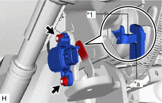
(2) Firmly depress the brake pedal and break the brake pedal stroke sensor lever set pin.
(3) Remove the broken lever set pin.
(4) Connect the connector.
(b) When reusing the brake pedal stroke sensor assembly:
| (1) Install the brake pedal stroke sensor assembly to the brake pedal support assembly and temporarily install the 2 nuts. NOTICE:
|
|
(2) Connect the connector.
3. CONNECT CABLE TO NEGATIVE AUXILIARY BATTERY TERMINAL
(a) Connect the negative (-) auxiliary battery terminal and tighten the nut.
Torque:
5.4 N·m {55 kgf·cm, 48 in·lbf}
4. ADJUST BRAKE PEDAL STROKE SENSOR ASSEMBLY
NOTICE:
When the brake pedal stroke sensor assembly is being reused, perform the following procedure to adjust it.
(a) Connect the Techstream to the DLC3.
(b) Turn the power switch on (IG).
(c) Turn the Techstream on.
(d) Enter the following menus: Chassis / ABS/VSC/TRAC / Data List / Stroke Sensor.
Chassis > ABS/VSC/TRAC > Data List| Tester Display |
|---|
| Stroke Sensor |
| (e) Read the stroke sensor value in the Data List, and turn the brake pedal stroke sensor assembly slowly to the right or left to adjust the output voltage so that it is within the following range. Standard Voltage (without the brake pedal depressed): 0.8 to 1.2 V |
|
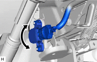
(f) Tighten the 2 nuts.
Torque:
8.5 N·m {87 kgf·cm, 75 in·lbf}
NOTICE:
Do not depress the brake pedal after turning the power switch on (IG).
(g) Turn the Techstream off and turn the power switch off.
(h) Disconnect the Techstream.
5. DISCONNECT CABLE FROM NEGATIVE AUXILIARY BATTERY TERMINAL
CAUTION:
- Wait at least 90 seconds after disconnecting the cable from the negative (-) auxiliary battery terminal to disable the SRS system.
- If the airbag deploys for any reason. it may cause a serious accident.
(a) Loosen the nut and disconnect the negative (-) auxiliary battery terminal.
6. INSTALL LOWER NO. 1 INSTRUMENT PANEL AIRBAG ASSEMBLY
Click here
7. CONNECT CABLE TO NEGATIVE AUXILIARY BATTERY TERMINAL
(a) Connect the negative (-) auxiliary battery terminal and tighten the nut.
Torque:
5.4 N·m {55 kgf·cm, 48 in·lbf}
8. INITIALIZATION AFTER RECONECTING AUXILIARY BATTERY TERMINAL
Click here
HINT:
When disconnecting and reconnecting the auxiliary battery, there is an automatic learning function that completes learning when the respective system is used.
Click here
9. INSTALL DECK FLOOR BOX LH
Click here
10. INSTALL REAR DECK FLOOR BOX
Click here
11. INSTALL NO. 3 DECK BOARD SUB-ASSEMBLY
Click here
12. CHECK AND CLEAR DTC
Click here
13. PERFORM INITIALIZATION AND CALIBRATION OF LINEAR SOLENOID VALVE
Click here
READ NEXT:
 Precaution
PRECAUTION TROUBLESHOOTING PRECAUTIONS (a) When there is a malfunction with terminal contact points or part installation problems, removal and installation of the suspected problem parts may return th
Parts Location
PARTS LOCATION ILLUSTRATION *A w/o AVS - - *1 FRONT AXLE HUB SUB-ASSEMBLY RH - FRONT SPEED SENSOR ROTOR RH *2 FRONT SPEED SENSOR RH *3 FRONT AXLE HUB SUB-ASSEMBLY LH - FRONT
SEE MORE:
Camshaft Position "A" - Timing Over-Advanced or System Performance (Bank 1) (P0011,P0012)
DESCRIPTION Refer to DTC P0010. Click here DTC No. Detection Item DTC Detection Condition Trouble Area MIL Memory P0011 Camshaft Position "A" - Timing Over-Advanced or System Performance (Bank 1) Intake valve timing is stuck at a certain value when in the advance range (1 trip
Oxygen (A/F) Sensor Pumping Current Circuit / Open (for A/F sensor) (Bank 1 Sensor 1) (P2237-P2239,P2252,P2253)
DESCRIPTION Refer to DTC P2195. Click here DTC No. Detection Item DTC Detection Condition Trouble Area MIL Memory P2237 Oxygen (A/F) Sensor Pumping Current Circuit / Open (for A/F sensor) (Bank 1 Sensor 1) An open in the circuit between terminals A1A+ and A1A- of the air fuel
