Lexus NX: Removal
REMOVAL
CAUTION / NOTICE / HINT
NOTICE:
- When the brake pedal is first depressed after replacing the brake pads or pushing back the disc brake piston, DTC C1214 may be output. As there is no malfunction, clear the DTC.
- While the auxiliary battery is connected, even if the power switch is off, the brake control system activates when the brake pedal is depressed or the door courtesy switch is turned on. Therefore, even if only brake shoes are to be removed and installed, be sure to perform the Disable Brake Control procedure and disconnect the cable from the negative (-) terminal of the auxiliary battery before beginning work.
HINT:
- Use the same procedure for the RH and LH sides.
- The procedure listed below is for the LH side.
PROCEDURE
1. PRECAUTION
NOTICE:
After turning the power switch off, waiting time may be required before disconnecting the cable from the negative (-) auxiliary battery terminal. Therefore, make sure to read the disconnecting the cable from the negative (-) auxiliary battery terminal notice before proceeding with work.
(Click here .gif) )
)
2. DISABLE BRAKE CONTROL
Click here
3. REMOVE REAR WHEEL
Click here
4. REMOVE REAR AXLE SHAFT NUT LH
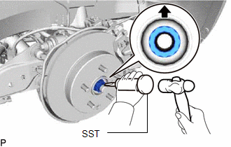
(a) Using SST and a hammer, unstake the staked part of the rear axle shaft nut.
SST: 09930-00010
09931-00010
09931-00020
NOTICE:
Loosen the staked part of the rear axle shaft nut completely, otherwise the screw of the drive shaft may be damaged.
(b) While applying the brakes, remove the rear axle shaft nut.
5. DISCONNECT REAR DISC BRAKE CALIPER ASSEMBLY LH
Click here
6. REMOVE REAR DISC
Click here
7. DISCONNECT REAR SPEED SENSOR LH
(a) w/ AVS:
Click here
(b) w/o AVS:
Click here
8. REMOVE REAR AXLE HUB AND BEARING ASSEMBLY LH
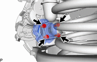
(a) Remove the 4 bolts from the rear axle carrier.
(b) Using a plastic-faced hammer, remove the rear axle hub and bearing assembly LH.
(c) Disconnect the rear disc brake dust cover sub-assembly LH from the rear axle carrier.
READ NEXT:
 Installation
INSTALLATION CAUTION / NOTICE / HINT NOTICE:
When the brake pedal is first depressed after replacing the brake pads or pushing back the disc brake piston, DTC C1214 may be output. As there is no ma
Rear Axle Hub Bolt
ComponentsCOMPONENTS ILLUSTRATION *1 REAR AXLE HUB BOLT LH *2 REAR DISC *3 REAR DISC BRAKE CALIPER ASSEMBLY LH - - N*m (kgf*cm, ft.*lbf): Specified torque ● Non-reusa
Steering Knuckle
ComponentsCOMPONENTS ILLUSTRATION *1 FRONT AXLE HUB SUB-ASSEMBLY LH *2 FRONT LOWER BALL JOINT ASSEMBLY LH *3 STEERING KNUCKLE LH *4 FRONT BRAKE DUST COVER N*m (kgf*cm, ft.*
SEE MORE:
Customize Parameters
CUSTOMIZE PARAMETERS CUSTOMIZE INTUITIVE PARKING ASSIST SYSTEM (a) Customizing with the Techstream. NOTICE:
When the customer requests a change in a function, first make sure that the function can be customized.
Be sure to make a note of the current settings before customizing.
When troublesh
System Diagram
SYSTEM DIAGRAM Communication Table Transmitter Receiver Signal Communication Method Air Conditioning Control Assembly Air Conditioning Amplifier Assembly Rear window defogger switch signal LIN
