Lexus NX: Installation
INSTALLATION
CAUTION / NOTICE / HINT
NOTICE:
- When the brake pedal is first depressed after replacing the brake pads or pushing back the disc brake piston, DTC C1214 may be output. As there is no malfunction, clear the DTC.
- While the auxiliary battery is connected, even if the power switch is off, the brake control system activates when the brake pedal is depressed or the door courtesy switch is turned on. Therefore, even if only brake shoes are to be removed and installed, be sure to perform the Disable Brake Control procedure and disconnect the cable from the negative (-) terminal of the auxiliary battery before beginning work.
HINT:
- Use the same procedure for the RH and LH sides.
- The procedure listed below is for the LH side.
PROCEDURE
1. INSTALL REAR AXLE HUB AND BEARING ASSEMBLY LH
(a) Install the rear disc brake dust cover sub-assembly LH to the rear axle carrier LH.
(b) Align the shaft splines and drive shaft to the axle hub and bearing assembly.
(c) Install the axle hub and bearing to the rear axle carrier with the 4 bolts.
Torque:
90 N·m {918 kgf·cm, 66 ft·lbf}
NOTICE:
Be careful not to damage the drive shaft boot and speed sensor rotor.
2. INSTALL REAR AXLE SHAFT NUT LH
(a) Clean the threaded parts on the drive shaft and a new axle shaft nut using a non-residue solvent.
NOTICE:
- Be sure to perform this work for a new drive shaft.
- Keep the threaded parts free of oil and foreign objects.
(b) Using a 30 mm socket wrench, install a new axle shaft nut.
Torque:
216 N·m {2203 kgf·cm, 159 ft·lbf}
HINT:
Stake the nut after inspecting for looseness and runout in the following steps.
3. INSPECT REAR AXLE HUB BEARING LOOSENESS
Click here .gif)
4. INSPECT REAR AXLE HUB RUNOUT
Click here
5. CONNECT REAR SPEED SENSOR LH
(a) w/ AVS:
Click here
(b) w/o AVS:
Click here
6. INSTALL REAR DISC
Click here
7. CONNECT REAR DISC BRAKE CALIPER ASSEMBLY LH
Click here
8. STAKE REAR AXLE SHAFT NUT LH
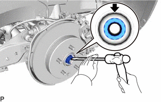
(a) Using a chisel and hammer, stake the rear axle shaft nut.
9. INSTALL REAR WHEEL
Click here
10. CONNECT CABLE TO NEGATIVE AUXILIARY BATTERY TERMINAL
(a) Connect the cable to the negative (-) auxiliary battery terminal and tighten the nut.
Torque:
5.4 N·m {55 kgf·cm, 48 in·lbf}
11. INSPECT AND ADJUST REAR WHEEL ALIGNMENT
Click here
12. CHECK FOR SPEED SENSOR SIGNAL
Click here
13. INITIALIZATION AFTER RECONECTING AUXILIARY BATTERY TERMINAL
Click here
HINT:
When disconnecting and reconnecting the auxiliary battery, there is an automatic learning function that completes learning when the respective system is used.
Click here
READ NEXT:
 Rear Axle Hub Bolt
ComponentsCOMPONENTS ILLUSTRATION *1 REAR AXLE HUB BOLT LH *2 REAR DISC *3 REAR DISC BRAKE CALIPER ASSEMBLY LH - - N*m (kgf*cm, ft.*lbf): Specified torque ● Non-reusa
Steering Knuckle
ComponentsCOMPONENTS ILLUSTRATION *1 FRONT AXLE HUB SUB-ASSEMBLY LH *2 FRONT LOWER BALL JOINT ASSEMBLY LH *3 STEERING KNUCKLE LH *4 FRONT BRAKE DUST COVER N*m (kgf*cm, ft.*
SEE MORE:
Immobiliser System does not Operate Properly
DESCRIPTION The immobiliser system compares the ID code that is registered in the certification ECU (smart key ECU assembly) with the ID code of the transponder chip that is embedded in the electrical key transmitter sub-assembly. WIRING DIAGRAM Click here CAUTION / NOTICE / HINT NOTICE:
When
How To Proceed With Troubleshooting
CAUTION / NOTICE / HINT HINT:
Use the following procedure to troubleshoot the automatic headlight beam level control system (for Triple Beam Headlight).
*: Use the Techstream
PROCEDURE 1. VEHICLE BROUGHT TO WORKSHOP
NEXT 2. CUSTOMER PROBLEM ANALYSIS AND SYMPTO
