Lexus NX: Steering Knuckle
Components
COMPONENTS
ILLUSTRATION
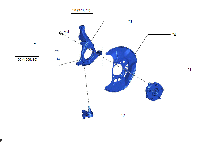
| *1 | FRONT AXLE HUB SUB-ASSEMBLY LH | *2 | FRONT LOWER BALL JOINT ASSEMBLY LH |
| *3 | STEERING KNUCKLE LH | *4 | FRONT BRAKE DUST COVER |
.png) | N*m (kgf*cm, ft.*lbf): Specified torque | ● | Non-reusable part |
Removal
REMOVAL
CAUTION / NOTICE / HINT
HINT:
- Use the same procedure for the RH and LH sides.
- The procedure listed below is for the LH side.
PROCEDURE
1. REMOVE FRONT AXLE HUB SUB-ASSEMBLY LH
Click here .gif)
2. REMOVE FRONT LOWER BALL JOINT ASSEMBLY LH
Click here
3. REMOVE STEERING KNUCKLE LH
(a) Secure the front axle assembly in a vise.
NOTICE:
When using a vise, do not overtighten it.
| (b) Remove the 4 bolts and front axle hub sub-assembly from the steering knuckle. NOTICE: Do not place the hub and bearing's magnet rotor side so that it is facing downward, and do not allow the magnet rotor side to become damaged or contact foreign matter. |
|
.png)
(c) Remove the front brake dust cover from the steering knuckle.
Installation
INSTALLATION
CAUTION / NOTICE / HINT
HINT:
- Use the same procedure for the RH and LH sides.
- The procedure listed below is for the LH side.
PROCEDURE
1. INSTALL STEERING KNUCKLE LH
(a) Secure the steering knuckle in a vise.
NOTICE:
When using a vise, do not overtighten it.
(b) Install the front brake dust cover to the steering knuckle.
(c) Install the front axle hub sub-assembly with the 4 bolts.
Torque:
96 N·m {979 kgf·cm, 71 ft·lbf}
NOTICE:
Do not place the hub and bearing's magnet rotor side so that it is facing downward, and do not allow the magnet rotor side to become damaged or contact foreign matter.
2. INSTALL FRONT LOWER BALL JOINT ASSEMBLY LH
Click here .gif)
3. INSTALL FRONT AXLE HUB SUB-ASSEMBLY LH
Click here
READ NEXT:
 Drive Shaft System
Problem Symptoms TablePROBLEM SYMPTOMS TABLE HINT: Use the table below to help determine the cause of problem symptoms. If multiple suspected areas are listed, the potential causes of the symptoms ar
SEE MORE:
Tire inflation pressure
Checking the specified tire inflation
pressure
The recommended cold tire inflation
pressure and tire size are displayed on
the tire and loading information label.
Inspection and adjustment procedure
Tire valve
Tire pressure gauge
1. Remove the tire valve cap.
2. Press the tip of
Components
COMPONENTS ILLUSTRATION *1 DECK FLOOR BOX LH *2 NO. 3 DECK BOARD SUB-ASSEMBLY *3 REAR DECK FLOOR BOX *4 NEGATIVE AUXILIARY BATTERY TERMINAL N*m (kgf*cm, ft.*lbf): Specified torque - - ILLUSTRATION *1 STEREO COMPONENT EQUALIZER ASSEMBLY *2 STEREO COMPONENT
