Lexus NX: Stereo Component Amplifier Disconnected (B15D3)
DESCRIPTION
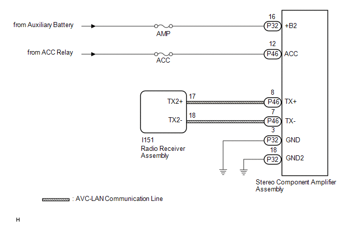
The radio receiver assembly and stereo component amplifier assembly are connected by the AVC-LAN communication line.
This DTC is stored when an AVC-LAN communication error occurs between the radio receiver assembly and stereo component amplifier assembly.
| DTC No. | Detection Item | DTC Detection Condition | Trouble Area |
|---|---|---|---|
| B15D3 | Stereo Component Amplifier Disconnected | A device that is listed in the AVC-LAN connected device record of the master unit is missing. |
|
HINT:
For the AVC-LAN communication line, the radio receiver assembly is the master unit.
WIRING DIAGRAM
CAUTION / NOTICE / HINT
NOTICE:
- Inspect the fuses for circuits related to this system before performing the following procedure.
-
When replacing the radio receiver assembly, always replace it with a new one.
If a radio receiver assembly which was installed to another vehicle is used, the following may occur:
- A communication malfunction DTC may be stored.
- The radio receiver assembly may not operate normally.
HINT:
Depending on the parts that are replaced during vehicle inspection or maintenance, performing initialization, registration or calibration may be needed. Refer to Precaution for Audio and Visual System.
Click here .gif)
PROCEDURE
| 1. | CHECK DTC |
(a) If DTC B15C3 is output, perform troubleshooting for DTC B15C3 first.
Body Electrical > Navigation System > Trouble CodesOK:
DTC B15C3 is not output.
| NG | .gif) | GO TO DTC B15C3 |
|
.gif)
| 2. | CHECK OPTIONAL COMPONENTS (INCLUDING ASSOCIATED WIRING) |
(a) Check that optional components (including associated wiring) which generate radio waves are not installed.
| Result | Proceed to |
|---|---|
| Optional components (including associated wiring) are installed. | A |
| Optional components (including associated wiring) are not installed. | B |
HINT:
- Electrical noise from radio waves generated by optional components or the wiring for those components may affect AVC-LAN communication.
- This DTC may be stored when a AVC-LAN communication error occurs due to electrical noise.
| B | | GO TO STEP 5 |
|
| 3. | REMOVE OPTIONAL COMPONENTS (INCLUDING ASSOCIATED WIRING) (INCLUDING ASSOCIATED WIRING) |
(a) Remove optional components (including associated wiring).
NOTICE:
Do not remove optional components or associated wiring without the permission of the customer.
|
| 4. | CHECK DTC |
(a) Clear the DTCs.
Click here
(b) Recheck for DTCs and check that no DTCs are output.
Click here
OK:
No DTCs are output.
| OK | | END (COMMUNICATION MALFUNCTION DUE TO NOISE) |
|
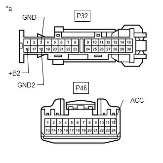
| 5. | CHECK HARNESS AND CONNECTOR (STEREO COMPONENT AMPLIFIER ASSEMBLY - BATTERY AND BODY GROUND) |
| (a) Disconnect the stereo component amplifier assembly connector. |
|
(b) Measure the resistance according to the value(s) in the table below.
Standard Resistance:
| Tester Connection | Condition | Specified Condition |
|---|---|---|
| P32-3 (GND) - Body ground | Always | Below 1 Ω |
| P32-18 (GND2) - Body ground | Always | Below 1 Ω |
(c) Measure the voltage according to the value(s) in the table below.
Standard Voltage:
| Tester Connection | Condition | Specified Condition |
|---|---|---|
| P32-16 (+B2) - Body ground | Power switch off | 11 to 14 V |
| NG | | REPAIR OR REPLACE HARNESS OR CONNECTOR |
|
| 6. | INSPECT RADIO RECEIVER ASSEMBLY (TX1+, TX1-) |
| (a) Remove the radio receiver assembly. Click here |
|
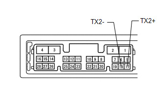
(b) Measure the resistance according to the value(s) in the table below.
Standard Resistance:
| Tester Connection | Condition | Specified Condition |
|---|---|---|
| 17 (TX2+) - 18 (TX2-) | Always | 60 to 80 Ω |
| NG | | REPLACE RADIO RECEIVER ASSEMBLY |
|
| 7. | CHECK HARNESS AND CONNECTOR (RADIO RECEIVER ASSEMBLY - STEREO COMPONENT AMPLIFIER ASSEMBLY) |
(a) Disconnect the I151 radio receiver assembly connector.
(b) Disconnect the P46 stereo component amplifier assembly connector.
(c) Measure the resistance according to the value(s) in the table below.
Standard Resistance:
| Tester Connection | Condition | Specified Condition |
|---|---|---|
| I151-17 (TX2+) - P46-8 (TX+) | Always | Below 1 Ω |
| I151-18 (TX2-) - P46-7 (TX-) | Always | Below 1 Ω |
| I151-17 (TX2+) - Body ground | Always | 10 kΩ or higher |
| I151-18 (TX2-) - Body ground | Always | 10 kΩ or higher |
| NG | | REPAIR OR REPLACE HARNESS OR CONNECTOR |
|
| 8. | CHECK STEREO COMPONENT AMPLIFIER ASSEMBLY |
(a) Replace the stereo component amplifier assembly with a new or known good one.
Click here
(b) Clear the DTCs.
Click here
(c) Recheck for DTCs and check that no DTCs are output.
Click here
OK:
No DTCs are output.
| OK | | END (STEREO COMPONENT AMPLIFIER ASSEMBLY IS DEFECTIVE) |
| NG | | REPLACE RADIO RECEIVER ASSEMBLY |
READ NEXT:
 Display Disconnected (B15D6)
DESCRIPTION The multi-display assembly and radio receiver assembly are connected by the AVC-LAN communication line. This DTC is stored when an AVC-LAN communication error occurs between the multi-disp
Telematics Transceiver Disconnected (B15DB)
DESCRIPTION If the radio receiver assembly cannot detect the DCM (telematics transceiver) for a certain period of time (90 seconds) after the power switch is turned on (IG) and the radio receiver asse
Air Conditioner ECU Vehicle Information Reading/Writing Processor Malfunction (B15F5)
DESCRIPTION This DTC is stored when items controlled by the air conditioning amplifier assembly cannot be customized via the audio and visual system vehicle customization screen. HINT: The air conditi
SEE MORE:
Dtc Check / Clear
DTC CHECK / CLEAR CHECK FOR DTCS (a) Connect the Techstream to the DLC3. (b) Turn the power switch on (IG). (c) Turn the Techstream on. (d) Enter the following menus: Powertrain / Hybrid Control / Trouble Codes. (e) Check the DTCs and freeze frame data, and then write them down. (f) Check the detail
DC/DC Converter Voltage Sensor "A" Range / Performance (P0E32-585)
DTC SUMMARY MALFUNCTION DESCRIPTION The hybrid vehicle control ECU detects a VL sensor malfunction. The cause of this malfunction may be one of the following: Inside of inverter voltage sensor circuit malfunction
Voltage sensor malfunction
Motor generator control ECU (MG ECU) malfunction
Comm
