- Mounted on the back door to transmit a composite image of the area behind the vehicle and guide lines calculated based on signals received from each ECU, to the multi-display.
- Has a color video camera that uses a Complementary Metal Oxide Semiconductor (CMOS) and a wide-angle lens.
- Stops displaying the guide lines when an open signal is received for the back door.
- Performs overall control of the system by receiving signals from the sensor and ECUs.
Lexus NX: System Description
Lexus NX Service Manual / Audio & Visual & Telematics / Park Assist / Monitoring / Parking Assist Monitor System / System Description
SYSTEM DESCRIPTION
GENERAL
(a) This system has a rear television camera assembly mounted on the back door to display an image of the area behind the vehicle on the display. The display panel also shows a composite view consisting of the area behind the vehicle and parking guide lines to assist the driver in parking the vehicle by monitoring the area behind the vehicle.
(b) This system consists of the following components:
(1) Rear television camera assembly
(2) Radio receiver assembly
(3) Multi-display assembly
(4) Steering sensor
(5) Hybrid Vehicle Control ECU
(6) Main body ECU (multiplex network body ECU)
(7) Blind spot monitor sensor LH*1
(8) Clearance warning ECU assembly*2
- *1: w/ Blind Spot Monitor System
- *2: w/ Intuitive Parking Assist System
(c) This system is equipped with a self-diagnosis system, which is operated from a designated window that appears on the multi-display.
FUNCTION OF COMPONENTS
(a) The radio receiver assembly controls the system by using information from the following components.
| Item | Function |
|---|---|
| Rear Television Camera Assembly | |
| Multi-display assembly |
|
| Radio Receiver Assembly | Transmits the setting information signal to the rear television camera assembly via CAN communication. |
| steering sensor | Detects the angle of the steering wheel and transmits the resulting signals to the rear television camera assembly via CAN communication. |
| ECM | Transmits the vehicle information signal to the rear television camera assembly via CAN communication. |
| Main Body ECU (Multiplex Network Body ECU) | Transmits a back door courtesy switch signal to the rear television camera assembly through CAN communication. |
| Blind Spot Monitor Sensor*1 | Transmits the RCTA information signal to the rear television camera assembly via CAN communication. |
| Clearance Warning ECU Assembly*2 | Transmits the sonar information signal to the rear television camera assembly via CAN communication. |
- *1: w/ Blind Spot Monitor System
- *2: w/ Intuitive Parking Assist System
OPERATION EXPLANATION
(a) The multi-display receives the reverse signal when the power switch on (IG) and the shift lever is moved to R. After receiving the reverse signal, the multi-display assembly switches to the parking assist monitor system.
DISPLAY MODE SETTING
(a) Rear view screen
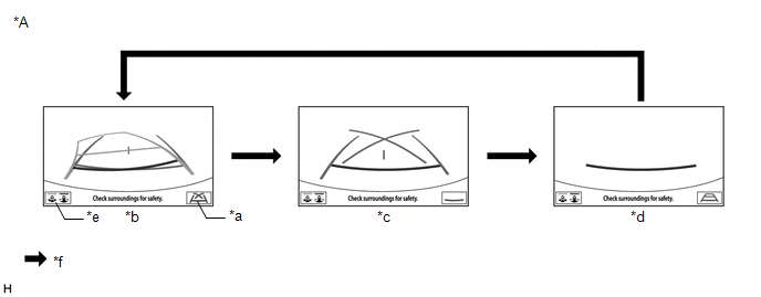
| *A | Example | - | - |
| *a | Display Mode Switch Screen Button | *b | Estimated Course Line Display Mode |
| *c | Parking Assist Guide Line Display Mode | *d | Distance Guide Line Display Mode |
| *e | Display Mode Switching Button | *f | Guide Line Display Mode Switching Button Pressed |
HINT:
The screen changes to the wide rear view screen when the display mode switching button is selected.
(1) While the parking assist monitor is displayed, pressing the display mode switch screen button switches the parking assist monitor display mode.
Parking Assist Monitor Display Mode| Parking Assist Monitor Display Mode | Distance Guide Lines (Red) | Estimated Course Lines (Yellow) | Distance Guide Line (Yellow) | Vehicle Width Guide Line (Blue) | Distance Guide Line (Blue) | Parking Assist Guide Lines (Blue) | Vehicle Center Guide Line (Blue) |
|---|---|---|---|---|---|---|---|
| Estimated course line display mode | Displayed | Displayed | Displayed | Displayed | Displayed | Not displayed | Displayed |
| Parking assist guide line display mode | Displayed | Not displayed | Not displayed | Displayed | Not displayed | Displayed | Displayed |
| Distance guide line display mode | Displayed | Not displayed | Not displayed | Not displayed | Not displayed | Not displayed | Not displayed |
(b) Wide rear view screen
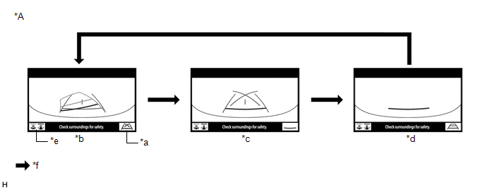
| *A | Example | - | - |
| *a | Guide Line Display Mode Switching Button | *b | Estimated Course Line Display Mode |
| *c | Parking Assist Guide Line Display Mode | *d | Distance Guide Line Display Mode |
| *e | Display Mode Switching Button | *f | Guide Line Display Mode Switching Button Pressed |
HINT:
The screen changes to the rear view screen when the display mode switching button is selected.
(1) While the parking assist monitor is displayed on the multi-display, pressing the guide line display mode switching button switches the parking assist monitor display mode.
Parking Assist Monitor Display Mode| Parking Assist Monitor Display Mode | Distance Guide Lines (Red) | Estimated Course Lines (Yellow) | Distance Guide Line (Yellow) | Vehicle Width Guide Line (Blue) | Distance Guide Line (Blue) | Parking Assist Guide Lines (Blue) | Vehicle Center Guide Line (Blue) |
|---|---|---|---|---|---|---|---|
| Estimated course line display mode | Displayed | Displayed | Displayed | Displayed | Displayed | Not displayed | Displayed |
| Parking assist guide line display mode | Displayed | Not displayed | Not displayed | Displayed | Not displayed | Displayed | Displayed |
| Distance guide line display mode | Displayed | Not displayed | Not displayed | Not displayed | Not displayed | Not displayed | Not displayed |
DIAGNOSTIC FUNCTION OUTLINE
(a) This parking assist monitor system has a diagnostic function displayed on the multi-display assembly. This function enables calibration (adjustment and verification) of the parking assist monitor system.
Click here .gif)
(b) The following items for the parking assist monitor system can be checked using the Techstream.
| Item | Proceed to |
|---|---|
| DTC | |
| Data List / Active Test | |
READ NEXT:
 How To Proceed With Troubleshooting
CAUTION / NOTICE / HINT HINT:
Use the following procedure to troubleshoot the parking assist monitor system.
*: Use the Techstream.
PROCEDURE 1. VEHICLE BROUGHT TO WORKSHOP
NEXT
Initialization
INITIALIZATION INITIALIZE PARKING ASSIST MONITOR SYSTEM (a) When the "!" mark is displayed on the multi-display assembly, correct the steering angle neutral point using the following method. (1) Fully
Calibration
CALIBRATION ADJUST PARKING ASSIST MONITOR SYSTEM (a) This parking assist monitor system can be adjusted using the diagnostic screen of the display. (b) If the following operations are performed, it is
SEE MORE:
Components
COMPONENTS ILLUSTRATION *A w/ Hands Free Power Back Door - - *1 NO. 2 LUGGAGE ROOM WIRE *2 REAR CENTER ULTRASONIC SENSOR *3 REAR CENTER ULTRASONIC SENSOR RETAINER *4 REAR CORNER ULTRASONIC SENSOR *5 REAR CORNER ULTRASONIC SENSOR RETAINER - - ● Non-reus
Components
COMPONENTS ILLUSTRATION -
*A w/ Damper - - *1 SUSPENSION TOWER DAMPER - - N*m (kgf*cm, ft.*lbf): Specified torque - - ILLUSTRATION w/ Damper
*A w/o Damper - - *1 SUSPENSION TOWER DAMPER - - N*m (kgf*cm, ft.*lbf): Specified torque - -
© 2016-2026 Copyright www.lexunx.com
