- Auto away/return state signal
- 3Tilt and telescopic position request signal
- Driver position data signal* (Driver seat, tilt and telescopic steering and mirror)
- IG SW signal
- Front seat inner belt (for driver) buckle switch signal
Lexus NX: System Diagram
Lexus NX Service Manual / Steering / Steering Column / Power Tilt And Power Telescopic Steering Column System / System Diagram
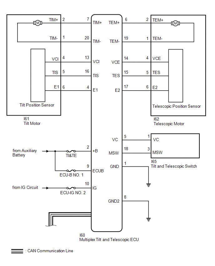
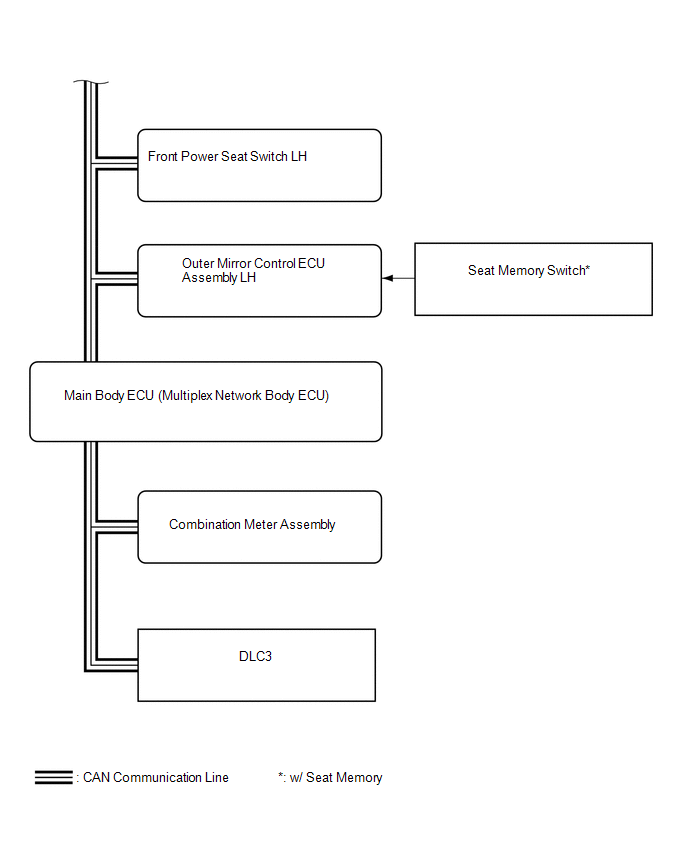
SYSTEM DIAGRAM
 Communication Table
 | Transmitting ECU (Transmitter) | Receiving ECU | Signal | Communication Method |
|---|---|---|---|
| Main Body ECU (Multiplex Network Body ECU) | Multiplex Tilt and Telescopic ECU | | CAN |
| Front Power Seat Switch LH | Multiplex Tilt and Telescopic ECU |
| |
| Combination Meter Assembly | Multiplex Tilt and Telescopic ECU | Vehicle speed signal | |
| Multiplex Tilt and Telescopic ECU | Main Body ECU (Multiplex Network Body ECU) | State signal of tilt and telescopic steering | |
| Multiplex Tilt and Telescopic ECU | Front Power Seat Switch LH |
|
- *: w/ Seat Memory
READ NEXT:
 How To Proceed With Troubleshooting
CAUTION / NOTICE / HINT HINT: *: Use the Techstream. PROCEDURE 1. VEHICLE BROUGHT TO WORKSHOP
NEXT 2. INSPECT AUXILIARY BATTERY VOLTAGE Standard voltage: 11 to 14 V
Customize Parameters
CUSTOMIZE PARAMETERS CUSTOMIZE POWER TILT AND POWER TELESCOPIC STEERING COLUMN SYSTEM HINT: The following items can be customized. NOTICE:
When the customer requests a change in a function, first m
Problem Symptoms Table
PROBLEM SYMPTOMS TABLE HINT:
Use the table below to help determine the cause of problem symptoms. If multiple suspected areas are listed, the potential causes of the symptoms are listed in order of
SEE MORE:
D-Seat ECU Vehicle Information Reading/Writing Process Malfunction (B15F8)
DESCRIPTION This DTC is stored when items controlled by the position control ECU assembly (driver seat) cannot be customized via the audio and visual system vehicle customization screen. HINT: The position control ECU assembly (driver seat) controls the front power seat control system (w/ Memory) re
Inspection
INSPECTION PROCEDURE 1. INSPECT CLEARANCE LIGHT ASSEMBLY LH (a) Apply battery voltage to the connector and check the light illumination condition. OK: Battery Connection Specified Condition Positive (+) → 3 (DRL) Negative (-) → 2 (E) Negative (-) → 4 (DRLC) White LED illuminates
© 2016-2026 Copyright www.lexunx.com
