Lexus NX: System Diagram
Lexus NX Service Manual / Vehicle Exterior / Door / Hatch / Back Door Closer System / System Diagram
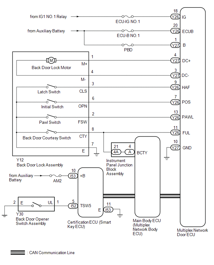
SYSTEM DIAGRAM
 Communication Table
 | Transmitting ECU | Receiver ECU | Signal | Communication Method |
|---|---|---|---|
| Certification ECU (Smart Key ECU Assembly) | Main Body ECU (Multiplex Network Body ECU) | Back door opener switch assembly signal | CAN |
| Main Body ECU (Multiplex Network Body ECU) | Multiplex Network Door ECU | Back door opener switch assembly signal | CAN |
READ NEXT:
 System Description
SYSTEM DESCRIPTION BACK DOOR CLOSER SYSTEM DESCRIPTION (a) Operating any back door opener switch assembly when the back door is fully closed inputs a request signal to the multiplex network door ECU.
How To Proceed With Troubleshooting
CAUTION / NOTICE / HINT HINT:
The back door closer system troubleshooting procedure is based on the premise that the power back door system is operating normally. Check the power back door system f
Operation Check
OPERATION CHECK CHECK BASIC FUNCTIONS (a) When the back door is partially closed, check that the motor operates to fully close (lock) the back door. (b) Check that the back door can be opened. (c) Whe
SEE MORE:
Diagnosis System
DIAGNOSIS SYSTEM CHECK DLC3 (a) Check the DLC3. Click here INSPECT AUXILIARY BATTERY VOLTAGE (a) Measure the auxiliary battery voltage with the power switch off. Standard voltage: 11 to 14 V If the voltage is below 11 V, recharge or replace the auxiliary battery.
Replacement
REPLACEMENT PROCEDURE 1. REPLACE INTAKE VALVE GUIDE BUSH (a) Heat the cylinder head sub-assembly to approximately 80 to 100°C (176 to 212°F). (b) Place the cylinder head sub-assembly on wooden blocks. (c) Using SST and a hammer, tap out the intake valve guide bush. SST: 09201-01055 SST: 09950-7
© 2016-2026 Copyright www.lexunx.com
