Lexus NX: System Description
SYSTEM DESCRIPTION
BACK DOOR CLOSER SYSTEM DESCRIPTION
(a) Operating any back door opener switch assembly when the back door is fully closed inputs a request signal to the multiplex network door ECU. The multiplex network door ECU outputs a "latch release" command to the back door lock assembly in response to the input.
(b) The latch can be released only when the back door is unlocked.
(c) 3 switches are built into the back door lock assembly, and the multiplex network door ECU monitors each switch status. The multiplex network door ECU controls latch "release/close" operations in response to the inputs from each switch.
| Switch | Function |
|---|---|
| Back door courtesy light switch | Detects whether back door is open or closed. This switch turns on when back door is open or ajar and turns off when it is fully closed. |
| Latch switch | Detects fully closed position of latch. This switch turns on when latch is in open-latch position. |
| Initial switch | Detects ajar position of latch. This switch turns on when latch is in half-latch position. |
FUNCTION OF MAIN COMPONENTS
| Component | Function |
|---|---|
| Multiplex network door ECU | The multiplex network door ECU controls the back door closer system in accordance with the signals received from the back door lock assembly. |
| Back door lock assembly | Receives an operation signal from the multiplex network door ECU to open/close the back door. |
CONSTRUCTION AND OPERATION
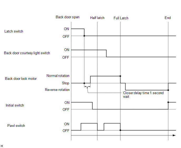
(a) Closing Operation
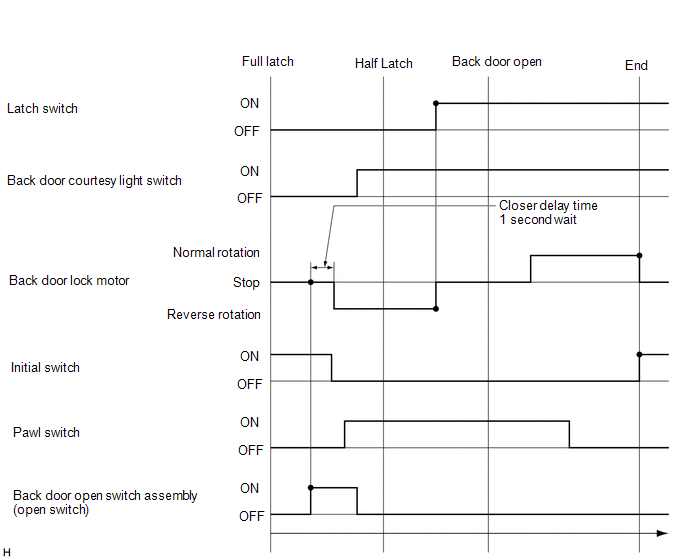
(b) Opening Operation
READ NEXT:
 How To Proceed With Troubleshooting
CAUTION / NOTICE / HINT HINT:
The back door closer system troubleshooting procedure is based on the premise that the power back door system is operating normally. Check the power back door system f
Operation Check
OPERATION CHECK CHECK BASIC FUNCTIONS (a) When the back door is partially closed, check that the motor operates to fully close (lock) the back door. (b) Check that the back door can be opened. (c) Whe
Problem Symptoms Table
PROBLEM SYMPTOMS TABLE HINT:
Use the table below to help determine the cause of problem symptoms. If multiple suspected areas are listed, the potential causes of the symptoms are listed in order of
SEE MORE:
Removal
REMOVAL PROCEDURE 1. REMOVE BACK DOOR CENTER GARNISH Click here 2. REMOVE BACK DOOR SIDE GARNISH LH Click here 3. REMOVE BACK DOOR SIDE GARNISH RH Click here 4. REMOVE BACK DOOR TRIM BASE (w/ Power Back Door) Click here 5. REMOVE PULL HANDLE (w/ Power Back Door) Click here 6. REMOVE B
Components
COMPONENTS ILLUSTRATION *A w/ AVS - - *1 FRONT AXLE HUB SUB-ASSEMBLY LH *2 FRONT AXLE SHAFT NUT LH *3 FRONT DISC *4 FRONT DISC BRAKE CALIPER ASSEMBLY LH *5 FRONT FLEXIBLE HOSE *6 FRONT LOWER NO. 1 SUSPENSION ARM SUB-ASSEMBLY LH *7 FRONT SPEED SENSOR LH
