Lexus NX: Terminals Of Ecu
TERMINALS OF ECU
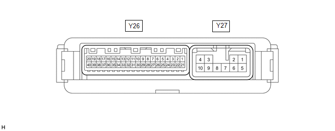
CHECK MULTIPLEX NETWORK DOOR ECU
(a) Disconnect the Y26 and Y27 multiplex network door ECU connectors.
(b) Measure the voltage and resistance according to the value(s) in the table below.
HINT:
Measure the values on the wire harness side with the connector disconnected.
| Terminal No. (Symbol) | Wiring Color | Terminal Description | Condition | Specified Condition |
|---|---|---|---|---|
| Y26-20 (ECUB) - Body ground | W - Body ground | Auxiliary battery power supply | Power switch off | 11 to 14 V |
| Y26-18 (IG) - Body ground | W - Body ground | IG power supply | Power switch on (IG) | 11 to 14 V |
| Power switch off | Below 1 V | |||
| Y27-1 (B) - Body ground | LA-W - Body ground | Auxiliary battery power supply | Power switch off | 11 to 14 V |
| Y27-10 (GND) - Body ground | W-B - Body ground | Body ground | Always | Below 1 Ω |
(c) Reconnect the Y26 and Y27 multiplex network door ECU connectors.
(d) Measure the voltage and waveform according to the value(s) in the table below.
| Terminal No. (Symbol) | Wiring Color | Terminal Description | Condition | Specified Condition |
|---|---|---|---|---|
| Y27-4 (DC+) - Y27-3 (DC-) | LA-BR - LA-R | Back door lock assembly (back door lock motor) circuit | Back door lock motor operating | 11 to 14 V |
| Back door lock motor not operating | Below 1 V | |||
| Y26-11 (FUL) - Body ground | W - Body ground | Back door lock assembly (back door courtesy switch) signal circuit | Back door closed → open | Pulse generation → Below 1 V |
| Y26-9 (HAF) - Body ground | G - Body ground | Back door lock assembly (latch switch) signal circuit | Back door closed → fully open | 11 to 14 V → Below 1 V |
| Y26-7 (POS) - Body ground | B - Body ground | Back door lock assembly (initial switch) signal circuit | Back door open → Back door closer operates → Back door closed | Below 1 V → 11 to 14 V → Below 1 V |
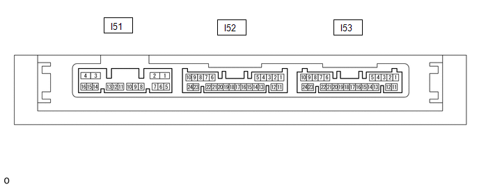
CHECK CERTIFICATION ECU (SMART KEY ECU ASSEMBLY)
(a) Disconnect the I53 certification ECU (smart key ECU assembly) connector.
(b) Measure the voltage and resistance according to the value(s) in the table below.
HINT:
Measure the values on the wire harness side with the connector disconnected.
| Terminal No. (Symbol) | Wiring Color | Terminal Description | Condition | Specified Condition |
|---|---|---|---|---|
| I53-10 (+B) - Body ground | W - Body ground | Auxiliary battery power supply | Power switch off | 11 to 14 V |
| I53-11 (E) - Body ground | W-B - Body ground | Body ground | Always | Below 1 Ω |
(c) Reconnect the I53 certification ECU (smart key ECU assembly) connector.
(d) Measure the voltage and waveform according to the value(s) in the table below.
| Terminal No. (Symbol) | Wiring Color | Terminal Description | Condition | Specified Condition |
|---|---|---|---|---|
| I52-5 (TSW5) - Body ground | Y - Body ground | Back door opener switch assembly signal | Back door opener switch assembly (open switch) off | Pulse generation |
| Back door opener switch assembly (open switch) on | Below 1 V |
READ NEXT:
 Dtc Check / Clear
DTC CHECK / CLEAR CHECK FOR DTC (a) Turn the power switch off. (b) Connect the Techstream to the DLC3. (c) Turn the power switch on (IG). (d) Turn the Techstream on. (e) Enter the following menus: Bod
Data List / Active Test
DATA LIST / ACTIVE TEST DATA LIST HINT: Using the Techstream to read the Data List allows the values or states of switches, sensors, actuators and other items to be read without removing any parts. Th
Diagnostic Trouble Code Chart
DIAGNOSTIC TROUBLE CODE CHART Back Door Closer System DTC No. Detection Item Link B2250 Back Door Closer Operation Malfunction B2251 Back Door Closer Switch Malfunction
SEE MORE:
Check For Intermittent Problems
CHECK FOR INTERMITTENT PROBLEMS CHECK FOR INTERMITTENT PROBLEMS HINT: A momentary interruption (open circuit) in the connectors and/or wire harnesses between the sensors and ECUs can be detected using the Data List function of the Techstream. (a) Turn the power switch off. (b) Connect the Techstream
Dtc Check / Clear
DTC CHECK / CLEAR CHECK DTC (a) Connect the Techstream to the DLC3. (b) Turn the power switch on (IG). (c) Turn the Techstream on. (d) Enter the following menus: Body Electrical / Telematics / Trouble Codes. Body Electrical > Telematics > Trouble Codes (e) Check the details of the DTC(s). Clic
