Lexus NX: Torque Sensor1 (C1511-C1514,C1517)
DESCRIPTION
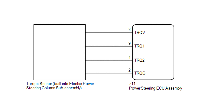
The torque sensor converts the steering wheel rotation torque into electric signals and sends them to the power steering ECU assembly.
| DTC No. | Detection Item | DTC Detection Condition | Trouble Area | Warning Indicate | Return-to-normal Condition | Note |
|---|---|---|---|---|---|---|
| C1511 | Torque Sensor1 | Torque sensor malfunction |
| On | Power switch on (IG) again | - |
| C1512 | Torque Sensor2 | Torque sensor malfunction |
| On | Power switch on (IG) again | - |
| C1513 | Torque Sensor Deviation Excessive | Torque sensor malfunction |
| On | Power switch on (IG) again | - |
| C1514 | Torque Sensor Power Supply Voltage | Torque sensor malfunction |
| On | Power switch on (IG) again | - |
| C1517 | Torque Hold | Torque sensor malfunction |
| On | Power switch on (IG) again | - |
WIRING DIAGRAM
CAUTION / NOTICE / HINT
NOTICE:
-
If the electric power steering column sub-assembly has been replaced, perform torque sensor zero point calibration.
Click here
.gif)
-
If the power steering ECU assembly has been replaced, perform assist map writing and torque sensor zero point calibration.
Click here
PROCEDURE
| 1. | CHECK CONNECTOR CONNECTION CONDITION |
(a) Check the connection condition of the torque sensor connector.
OK:
Torque sensor connector is securely connected to the power steering ECU assembly.
| NG | .gif) | CONNECT CONNECTOR |
|
.gif)
| 2. | CHECK POWER STEERING ECU ASSEMBLY (TRQV VOLTAGE) |
| (a) Turn the power switch on (IG). |
|
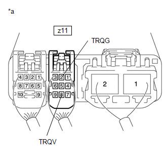
(b) Measure the voltage according to the value(s) in the table below.
Standard Voltage:
| Tester Connection | Switch Condition | Specified Condition |
|---|---|---|
| z11-8 (TRQV) - z11-2 (TRQG) | Power switch on (IG) | 4.5 to 5.5 V |
| NG | | REPLACE POWER STEERING ECU ASSEMBLY |
|
| 3. | CHECK POWER STEERING ECU ASSEMBLY (TRQ1, TRQ2 VOLTAGE) |
| (a) Turn the power switch on (READY). |
|
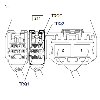
(b) Measure the voltage according to the value(s) in the table below.
Standard Voltage:
| Tester Connection | Condition | Specified Condition |
|---|---|---|
| z11-9 (TRQ1) - z11-2 (TRQG) | Power switch on (READY), steering wheel not being turned (without load) | 2.3 to 2.7 V |
| Power switch on (READY), steering wheel being turned to the right with vehicle stopped | 2.5 to 3.8 V | |
| Power switch on (READY), steering wheel being turned to the left with vehicle stopped | 1.2 to 2.5 V | |
| z11-1 (TRQ2) - z11-2 (TRQG) | Power switch on (READY), steering wheel not being turned (without load) | 2.3 to 2.7 V |
| Power switch on (READY), steering wheel being turned to the right with vehicle stopped | 1.2 to 2.5 V | |
| Power switch on (READY), steering wheel being turned to the left with vehicle stopped | 2.5 to 3.8 V |
(c) Under each condition, measure the voltage according to the value(s) in the table below, and calculate the sum.
Standard Voltage:
| Tester Connection | Condition | Specified Condition |
|---|---|---|
| Sum of voltage between z11-9 (TRQ1) and z11-2 (TRQG) and voltage between z11-1 (TRQ2) and z11-2 (TRQG) | Power switch on (READY), steering wheel not being turned (without load) | Between 4.75 V and 5.25 V |
| Power switch on (READY), steering wheel being turned to the right with vehicle stopped | ||
| Power switch on (READY), steering wheel being turned to the left with vehicle stopped |
| OK | | REPLACE POWER STEERING ECU ASSEMBLY |
| NG | | REPLACE ELECTRIC POWER STEERING COLUMN SUB-ASSEMBLY |
READ NEXT:
 Torque Sensor Zero Point Adjustment Undone (C1515,C1516)
DESCRIPTION These DTCs do not indicate a malfunction. The power steering ECU assembly stores C1515 when it determines that torque sensor zero point calibration has not been performed. The power steeri
Short in Motor Circuit (C1521-C1524,C1528,C1531-C1555)
DESCRIPTION The power steering ECU assembly detects steering force using the signal received from the steering torque sensor, and also monitors the motor circuit for errors. DTC No. Detection Ite
Vehicle Speed Signal (C1541)
DESCRIPTION The power steering ECU assembly receives vehicle speed signals from the skid control ECU (brake booster with master cylinder assembly) via CAN communication. The ECU provides appropriate a
SEE MORE:
Data List / Active Test
DATA LIST / ACTIVE TEST DATA LIST NOTICE: In the table below, the values listed under "Normal Condition" are reference values. Do not depend solely on these reference values when deciding whether a part is faulty or not. HINT: Using the Techstream to read the Data List allows the values or states of
Installation
INSTALLATION PROCEDURE 1. INSTALL BLOWER ASSEMBLY (a) Attach the 2 claws to install the blower assembly. (b) Install the 2 screws. (c) Attach the 3 clamps to install the air conditioning harness assembly. (d) Connect the No. 1 blower damper servo sub-assembly connector. 2. INSTALL AIR CONDITIONING U
