Lexus NX: Touch Pad Sensor Malfunction (B1559)
DESCRIPTION
This DTC is stored if the remote operation controller assembly (remote touch) detects a malfunction in itself, such as internal hardware failure or touch pad sensor malfunction.
| DTC No. | Detection Item | DTC Detection Condition | Trouble Area |
|---|---|---|---|
| B1559 | Touch Pad Sensor Malfunction | Internal touch pad sensor malfunction | Remote operation controller assembly (remote touch) |
PROCEDURE
| 1. | CHECK DTC |
(a) Clear the DTCs.
Click here .gif)
(b) Recheck for DTCs and check that no DTCs are output.
Click here
OK:
No DTCs are output.
HINT:
-
If DTC B155B is output, perform troubleshooting for DTC B155B first.
Click here
- Touch pad touch detection is performed using the electrostatic sensor and G sensor. However, there is no effect on the basic functions of the touch pad when the G sensor is not operating. Therefore, a counter is used to prevent DTCs from being output immediately (in order to reduce excessive DTC output). Therefore, when DTCs are not output, it is necessary to turn the power switch from on (ACC) to off and check for DTCs again.
| OK | .gif) | USE SIMULATION METHOD TO CHECK |
|
.gif)
| 2. | REMOTE TOUCH SELF CHECK (CHECK TOUCH SCREEN OPERATION POSITION RECOGNITION CONDITION) |
(a) Enter self-diagnostic mode.
Click here
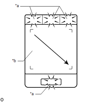
| (b) Operate the remote touch screen diagonally from the upper left to the lower right and check that the brightness of the switch illumination changes. NOTICE: Since the remote touch screen may recognize a pinch in/out operation if operated with 2 fingers, always use 1 finger to operate the remote touch in self-diagnostic mode. OK: Brightness changes according to touch screen operation.
|
|
| B | | REPLACE REMOTE OPERATION CONTROLLER ASSEMBLY (REMOTE TOUCH) |
|
| 3. | CHECK DTC |
(a) Clear the DTCs.
Click here
(b) Turn the power switch off.
(c) Turn the power switch on (ACC) and wait for 40 seconds.
(d) Recheck for DTCs and check that no DTCs are output.
Click here
OK:
No DTCs are output.
HINT:
Touch pad touch detection is performed using the electrostatic sensor and G sensor. However, there is no effect on the basic functions of the touch pad when the G sensor is not operating. Therefore, a counter is used to prevent DTCs from being output immediately (in order to reduce excessive DTC output). Therefore, when DTCs are not output, it is necessary to turn the power switch from on (ACC) to off and check for DTCs again.
| OK | | USE SIMULATION METHOD TO CHECK |
| NG | | REPLACE REMOTE OPERATION CONTROLLER ASSEMBLY (REMOTE TOUCH) |
READ NEXT:
 Touch Pad Vibration Driver Malfunction (B155A)
DESCRIPTION This DTC is stored if the remote operation controller assembly (remote touch) detects a malfunction in itself, such as internal hardware failure or touch pad vibration driver malfunction.
Touch Pad Memory Module Malfunction (B155B)
DESCRIPTION This DTC is stored if the remote operation controller assembly (remote touch) detects a malfunction in itself, such as internal hardware failure or touch pad memory module malfunction.
GVIF Disconnected (from EMV/MM Integrated Device to Multi Display) (B1575)
DESCRIPTION DTC No. Detection Item DTC Detection Condition Trouble Area B1575 GVIF Disconnected (from EMV/MM Integrated Device to Multi Display) GVIF disconnected (from radio receiver
SEE MORE:
Evaporative Emission Control System Incorrect Purge Flow (P0441)
DTC SUMMARY DTC No. Detection Item DTC Detection Condition Trouble Area MIL Memory P0441 Evaporative Emission Control System Incorrect Purge Flow One of the following conditions met:
Leak detection pump creates negative pressure (vacuum) in EVAP system and EVAP system pressur
Components
COMPONENTS ILLUSTRATION *1 DECK FLOOR BOX LH *2 NO. 3 DECK BOARD SUB-ASSEMBLY *3 REAR DECK FLOOR BOX *4 NEGATIVE AUXILIARY BATTERY TERMINAL N*m (kgf*cm, ft.*lbf): Specified torque - - ILLUSTRATION *A for 8 Inch - - *1 INSTRUMENT PANEL FINISH PLATE
