Lexus NX: VSC OFF Switch Circuit
DESCRIPTION
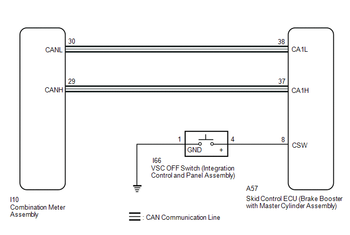
The skid control ECU assembly is connected to the combination meter assembly via CAN communication.
Pressing the VSC OFF switch turns off TRAC operation, and pressing and holding this switch turns off TRAC and VSC operation. If TRAC and VSC operations are turned off, the TRAC OFF message will be displayed on the multi-information display and the VSC OFF indicator light will come on.
WIRING DIAGRAM
CAUTION / NOTICE / HINT
NOTICE:
When replacing the skid control ECU (brake booster with master cylinder assembly), perform initialization and calibration of the linear solenoid valve.
Click here .gif)
PROCEDURE
| 1. | CHECK CAN COMMUNICATION SYSTEM |
(a) Check if CAN communication system DTCs are output.
Click here
| Result | Proceed to |
|---|---|
| DTCs are not output. | A |
| DTCs are output. | B |
| B | .gif) | INSPECT CAN COMMUNICATION SYSTEM |
|
.gif)
| 2. | CHECK IF SKID CONTROL ECU ASSEMBLY CONNECTOR IS SECURELY CONNECTED |
(a) Check if the skid control ECU assembly (brake booster with master cylinder assembly) connector is securely connected.
OK:
The connector is securely connected.
| NG | | CONNECT CONNECTOR TO SKID CONTROL ECU ASSEMBLY CORRECTLY |
|
| 3. | READ VALUE USING TECHSTREAM (TRAC/VSC OFF MODE) |
(a) Connect the Techstream to the DLC3.
(b) Turn the power switch on (IG).
(c) Select the Data List on the Techstream.
Click here
| Tester Display | Measurement Item | Range | Normal Condition | Diagnostic Note |
|---|---|---|---|---|
| TRAC/VSC Off Mode | TRAC/VSC off mode | Normal, TRAC OFF, Unknown or VSC OFF | Normal: Normal mode TRAC OFF: TRAC off mode VSC OFF: VSC off mode | Unknown: Unspecified |
| Tester Display |
|---|
| TRAC/VSC Off Mode |
(d) Check the indicator light and mode condition on the Techstream changes according to VSC OFF switch (integration control and panel assembly) operation.
Standard:
| Switch Operation | Mode Condition Display | Multi-information Display (TRAC OFF Message) | VSC OFF Indicator Light |
|---|---|---|---|
| Not pressed | Normal | Not displayed | Does not come on |
| Pressing the VSC OFF switch | TRAC OFF | Displayed | Does not come on |
| Pressing and holding the VSC OFF switch | VSC OFF | Displayed | Comes on |
| Result | Proceed to |
|---|---|
| Indicator light and mode condition display do not change. | A |
| Mode condition display is normal, but indicator light does not change. | B |
| Indicator light and mode condition display is normal. | C |
| B | | INSPECT METER / GAUGE SYSTEM |
| C | | USE SIMULATION METHOD TO CHECK |
|
| 4. | PERFORM ACTIVE TEST USING TECHSTREAM (MULTI-INFORMATION DISPLAY AND VSC OFF INDICATOR LIGHT) |
(a) Select the Active Test on the Techstream.
Click here
| Tester Display | Measurement Item | Control Range | Diagnostic Note |
|---|---|---|---|
| TRC(TRAC) OFF Indicator Light | Multi-information display (TRAC OFF message) | Display ON/OFF | Observe combination meter assembly |
| VSC OFF Indicator Light | VSC OFF indicator light | Indicator light ON/OFF | Observe combination meter assembly |
| Tester Display |
|---|
| TRC(TRAC) OFF Indicator Light |
| Tester Display |
|---|
| VSC OFF Indicator Light |
(b) Check the multi-information display (TRAC OFF message) and VSC OFF indicator light on the combination meter assembly turns ON or OFF in accordance with the Techstream operation.
OK:
The multi-information display (TRAC OFF message) and VSC OFF indicator light turns ON or OFF in accordance with the Techstream operation.
| NG | | GO TO STEP 7 |
|
| 5. | INSPECT INTEGRATION CONTROL AND PANEL ASSEMBLY |
(a) Turn the power switch off.
(b) Remove the VSC OFF switch (integration control and panel assembly).
Click here
(c) Inspect the VSC OFF switch (integration control and panel assembly).
Click here
OK:
The VSC OFF switch (integration control and panel assembly) operates normally.
| NG | | REPLACE INTEGRATION CONTROL AND PANEL ASSEMBLY |
|
| 6. | CHECK HARNESS AND CONNECTOR (BRAKE BOOSTER WITH MASTER CYLINDER ASSEMBLY - INTEGRATION CONTROL AND PANEL ASSEMBLY) |
(a) Disconnect the A57 skid control ECU (brake booster with master cylinder assembly) connector.
(b) Measure the resistance according to the value(s) in the table below.
Standard Resistance:
| Tester Connection | Condition | Specified Condition |
|---|---|---|
| A57-8 (CSW) - I66-4 (+) | Always | Below 1 Ω |
| A57-8 (CSW) or I66-4 (+) - Body ground | Always | 10 kΩ or higher |
| I66-1 (GND) - Body ground | Always | Below 1 Ω |
HINT:
If troubleshooting has been carried out according to Problem Symptoms Table, refer back to the table and proceed to the next step.
Click here
| OK | | REPLACE BRAKE BOOSTER WITH MASTER CYLINDER ASSEMBLY |
| NG | | REPAIR OR REPLACE HARNESS OR CONNECTOR |
| 7. | INSPECT COMBINATION METER ASSEMBLY |
(a) Turn the power switch off.
(b) Perform the Active Test of the combination meter assembly (meter CPU) using the Techstream.
Click here
| Tester Display |
|---|
| Meter Display 1 |
| Tester Display |
|---|
| Indicat. VSC OFF |
(c) Check the combination meter assembly.
OK:
The multi-information display and VSC OFF indicator light turns on or off in accordance with the Techstream operation.
| OK | | REPLACE BRAKE BOOSTER WITH MASTER CYLINDER ASSEMBLY |
| NG | | INSPECT METER / GAUGE SYSTEM |
READ NEXT:
 Components
COMPONENTS ILLUSTRATION *A w/ AVS - - *1 FRONT SKID CONTROL SENSOR WIRE LH *2 FRONT SPEED SENSOR LH N*m (kgf*cm, ft.*lbf): Specified torque - - ILLUSTRATION *A
Removal
REMOVAL CAUTION / NOTICE / HINT HINT:
Use the same procedure for the LH side and RH side.
The following procedure is for the LH side.
PROCEDURE 1. REMOVE FRONT TIRE Click here 2. REMOVE FRON
SEE MORE:
Removal
REMOVAL PROCEDURE 1. REMOVE CONSOLE ARMREST ASSEMBLY Click here 2. REMOVE UPPER REAR CONSOLE PANEL Click here 3. REMOVE UPPER NO. 2 CONSOLE PANEL GARNISH Click here 4. REMOVE UPPER NO. 1 CONSOLE PANEL GARNISH Click here 5. REMOVE INSTRUMENT SIDE PANEL LH Click here 6. REMOVE NO. 1
Installation
INSTALLATION CAUTION / NOTICE / HINT NOTICE:
Always use a new grommet and valve core when installing the tire pressure warning valve and transmitter.
Check that the washer and nut are not damaged, and replace them if necessary.
Make sure not to damage the urethane covered backside of the tire
