Lexus NX: Removal
REMOVAL
CAUTION / NOTICE / HINT
HINT:
- Use the same procedure for the LH side and RH side.
- The following procedure is for the LH side.
PROCEDURE
1. REMOVE FRONT TIRE
Click here .gif)
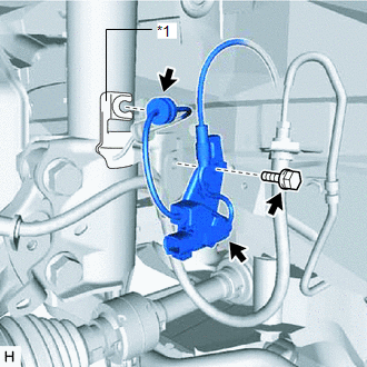
2. REMOVE FRONT SPEED SENSOR LH (w/ AVS)
| (a) Disconnect the connector. |
|
(b) Remove the bolt and sensor clamp from the steering knuckle.
(c) Remove the bolt and front speed sensor LH from the steering knuckle.
NOTICE:
Prevent foreign matter from attaching to the front speed sensor LH tip.
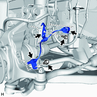
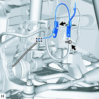
3. REMOVE FRONT SKID CONTROL SENSOR WIRE LH (w/ AVS)
| (a) Fold back the fender liner and disconnect the connector. |
|
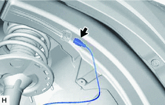
| (b) Remove the clamp. |
|
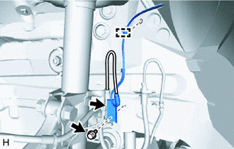
(c) Remove the bolt and sensor clamp from the side member.
| (d) Disconnect the connector from the absorber control actuator. |
|
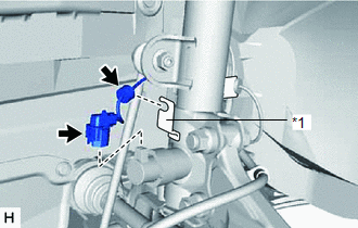
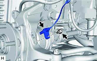
(e) Remove the grommet from the absorber bracket.
| (f) Remove the bolt, hook and sensor clamp. |
|
(g) Remove the grommet from the absorber bracket.
4. REMOVE FRONT SPEED SENSOR LH (w/o AVS)
| (a) Fold back the fender liner and disconnect the connector. |
|
| (b) Remove the clamp. |
|
(c) Remove the bolt and sensor clamp from the side member.
| (d) Remove the clamp. |
|
(e) Remove the bolt and sensor clamp from the absorber bracket.
| (f) Remove the bolt and front speed sensor LH from the steering knuckle. NOTICE: Prevent foreign matter from attaching to the front speed sensor LH tip. |
|
READ NEXT:
 Installation
INSTALLATION CAUTION / NOTICE / HINT HINT:
Use the same procedure for the LH side and RH side.
The following procedure is for the LH side.
PROCEDURE 1. INSTALL FRONT SKID CONTROL SENSOR WIRE L
Components
COMPONENTS ILLUSTRATION *A w/ AVS - - *1 REAR SPEED SENSOR LH - - N*m (kgf*cm, ft.*lbf): Specified torque - - ILLUSTRATION *A w/o AVS - - *1 REAR SPEE
SEE MORE:
High Voltage Power Resource (P3004-803)
DTC SUMMARY MALFUNCTION DESCRIPTION The hybrid vehicle control ECU monitors the high-voltage wiring between the HV battery and inverter with converter assembly and detects an open circuit malfunction. HINT:
This DTC is differentiated from P3004-131 based on detection timing (after power switch is
How To Proceed With Troubleshooting
CAUTION / NOTICE / HINT HINT:
Before performing troubleshooting for the dynamic radar cruise control system, perform troubleshooting for the pre-collision system.
Click here
*: Use the Techstream.
PROCEDURE 1. VEHICLE BROUGHT TO WORKSHOP
NEXT 2. PRE-CHECK
