Lexus NX: Wireless Door Lock Buzzer
Components
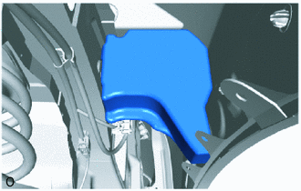
COMPONENTS
ILLUSTRATION
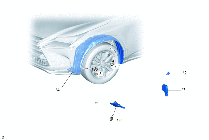
| *1 | FRONT FENDER SPLASH SHIELD FRONT LH | *2 | WIRELESS DOOR LOCK BUZZER |
| *3 | FRONT SIDE AIR GUIDE SUB-ASSEMBLY LH | *4 | FRONT FENDER LINER LH |
Installation
INSTALLATION
PROCEDURE
1. INSTALL WIRELESS DOOR LOCK BUZZER
(a) Attach the clamp and install the wireless door lock buzzer.
(b) Connect the connector.
(c) Install the front side air guide sub-assembly LH.
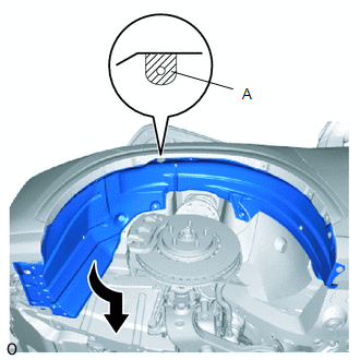
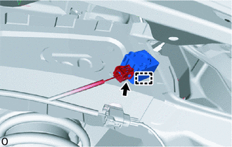
| (d) Return the front fender liner LH to its original position as shown in the illustration. NOTICE: Take care not to deform part A of the front fender liner LH as that part is easily damaged. |
|
(e) Attach the 8 clips.
(f) Using a 4 mm hexagon wrench, install the 2 hexagon screws.
2. INSTALL FRONT FENDER SPLASH SHIELD FRONT LH
Click here .gif)
Removal
REMOVAL
PROCEDURE
1. REMOVE FRONT FENDER SPLASH SHIELD FRONT LH
Click here .gif)
2. REMOVE WIRELESS DOOR LOCK BUZZER
| (a) Using a clip remover, detach the 8 clips. |
|
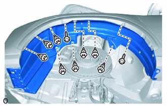
(b) Using a 4 mm hexagon wrench, remove the 2 hexagon screws.
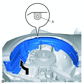
| (c) Slide the front fender liner LH toward the rear of the vehicle and down to create a clearance as shown in the illustration. NOTICE: Take care not to deform part A of the front fender liner LH as that part is easily damaged. |
|
| (d) Remove the front side air guide sub-assembly LH. |
|
| (e) Disconnect the connector. |
|
(f) Detach the clamp and remove the wireless door lock buzzer.
READ NEXT:
 Precaution
PRECAUTION PRECAUTIONS WHEN USING TECHSTREAM (a) When using the Techstream with the vehicle power switch off, connect the Techstream to the DLC3 and turn a courtesy light switch on and off at interval
Parts Location
PARTS LOCATION ILLUSTRATION *1 ENGINE ROOM RELAY BLOCK
- AM2 FUSE
*2 WIRELESS DOOR LOCK BUZZER *3 DOOR CONTROL RECEIVER - - ILLUSTRATION *A w/o Power Back Door Syste
SEE MORE:
Installation
INSTALLATION CAUTION / NOTICE / HINT HINT:
Use the same procedure for the RH and LH sides.
The procedure listed below is for the LH side.
PROCEDURE 1. INSTALL FRONT DOOR OUTSIDE MOULDING SUB-ASSEMBLY LH (a) Attach the 3 claws to install the front door outside moulding sub-assembly LH. (b) In
Battery Control System (P3000-388)
DESCRIPTION The hybrid vehicle control ECU alerts the driver and performs fail-safe control based on error signals received from the battery voltage sensor. This DTC is stored when the SOC (state of charge) of the HV battery starts to drop as a result of leaving the shift lever in N, running out of
