Lexus NX: Installation
INSTALLATION
CAUTION / NOTICE / HINT
HINT:
- Use the same procedure for the RH and LH sides.
- The procedure listed below is for the LH side.
PROCEDURE
1. INSTALL FRONT DOOR OUTSIDE MOULDING SUB-ASSEMBLY LH
(a) Attach the 3 claws to install the front door outside moulding sub-assembly LH.
(b) Install a nose piece to an air riveter or hand riveter.
(c) Insert the mandrel part of a new rivet into the nose piece.
(d) Place the riveter upright against the front door outside moulding sub-assembly LH and install the 6 rivets.
NOTICE:
-
Do not pry the rivet with the riveter as this will cause damage to the riveter and mandrel.
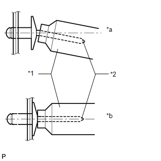
*1
Riveter
*2
Mandrel
*a
INCORRECT
*b
CORRECT
-
Confirm that the rivets are seated properly against the front door outside moulding sub-assembly LH.
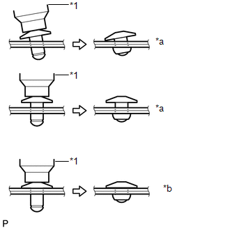
*1
Riveter
*a
INCORRECT
*b
CORRECT
- Do not tilt the riveter when installing the rivet to the front door outside moulding sub-assembly LH.
- Do not leave any space between the rivet head and front door outside moulding sub-assembly LH.
-
Do not leave any space between the front door outside moulding sub-assembly LH and front door panel. Firmly hold together the 2 items while installing the rivet.
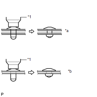
*1
Riveter
*a
INCORRECT
*b
CORRECT
HINT:
If the rivet cannot be cut, pull it once and cut it.
2. INSTALL FRONT DOOR REAR WINDOW FRAME MOULDING LH
HINT:
When installing the front door rear window frame moulding LH, heat the front door panel and front door rear window frame moulding LH using a heat light.
Standard:
| Item | Temperature |
|---|---|
| Front Door Panel | 40 to 60°C (104 to 140°F) |
| Front Door Rear Window Frame Moulding LH | 20 to 30°C (68 to 86°F) |
NOTICE:
Do not heat the front door panel and front door rear window frame moulding LH excessively.
(a) Clean the front door panel surface.
(1) Using a heat light, heat the front door panel surface.
(2) Remove the double-sided tape from the front door panel surface.
(3) Wipe off any tape adhesive residue with cleaner.
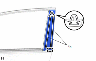
(b) Install a new front door rear window frame moulding LH.
(1) Using a heat light, heat a new front door rear window frame moulding LH and the front door panel surface.
(2) Remove the peeling paper from the face of the front door rear window frame moulding LH.
HINT:
After removing the peeling paper, keep the exposed adhesive free from foreign matter.
| (3) Attach the clip and guide to install the front door rear window frame moulding LH. HINT: Press the front door rear window frame moulding LH firmly to install it. |
|
3. INSTALL FRONT DOOR FIX WINDOW GLASS LH
Click here .gif)
4. INSTALL FRONT DOOR FRONT LOWER FRAME SUB-ASSEMBLY LH
Click here
5. INSTALL UPPER DOOR FRAME GARNISH LH
Click here
6. INSTALL FRONT DOOR WEATHERSTRIP LH
Click here
7. CONNECT FRONT DOOR CHECK ASSEMBLY LH
Click here
8. INSTALL OUTER MIRROR CONTROL ECU ASSEMBLY
Click here
9. INSTALL FRONT DOOR BELT MOULDING ASSEMBLY LH
Click here
10. INSTALL FRONT DOOR GLASS SUB-ASSEMBLY LH
Click here
11. INSTALL FRONT DOOR GLASS RUN LH
Click here
12. INSTALL FRONT DOOR SERVICE HOLE COVER LH
Click here
13. INSTALL FRONT DOOR ARMREST SET BRACKET LH
Click here
14. INSTALL FRONT DOOR INNER GLASS WEATHERSTRIP LH
Click here
15. INSTALL FRONT DOOR TRIM BOARD SUB-ASSEMBLY LH
Click here
16. INSTALL POWER WINDOW REGULATOR MASTER SWITCH ASSEMBLY WITH FRONT DOOR ARMREST BASE PANEL
Click here
17. INSTALL FRONT DOOR INSIDE HANDLE BEZEL PLUG LH
Click here
18. INSTALL FRONT DOOR TRIM COVER LH
Click here
19. CONNECT CABLE TO NEGATIVE AUXILIARY BATTERY TERMINAL
NOTICE:
When disconnecting the cable, some systems need to be initialized after the cable is reconnected.
Click here
20. INITIALIZATION AFTER RECONNECTING AUXILIARY BATTERY TERMINAL
Click here
HINT:
When disconnecting and reconnecting the auxiliary battery, there is an automatic learning function that completes learning when the respective system is used.
Click here
21. INSTALL DECK FLOOR BOX LH
Click here
22. INSTALL REAR DECK FLOOR BOX
Click here
23. INSTALL NO. 3 DECK BOARD SUB-ASSEMBLY
Click here
24. INITIALIZE POWER WINDOW CONTROL SYSTEM
Click here
25. CHECK POWER WINDOW CONTROL SYSTEM
Click here
READ NEXT:
 Components
COMPONENTS ILLUSTRATION *A for Sport Package - - *1 BACK DOOR NAME PLATE *2 BACK DOOR NO. 2 NAME PLATE *3 REAR BODY NO. 4 NAME PLATE *4 SYMBOL EMBLEM ● Non-reusab
Removal
REMOVAL PROCEDURE 1. REMOVE SYMBOL EMBLEM HINT: When removing the symbol emblem, heat the back door outside garnish sub-assembly and symbol emblem using a heat light. Standard: Item Temperature
SEE MORE:
Power Steering Warning Light Circuit
DESCRIPTION The power steering ECU is connected to the combination meter via CAN communication. If any of the following conditions are detected, the power steering warning light remains on.
The circuit that supplies power source voltage to the power steering ECU assembly (terminal IG) is open.
Data List / Active Test
DATA LIST / ACTIVE TEST DATA LIST NOTICE: In the table below, the values listed under "Normal Condition" are reference values. Do not depend solely on these reference values when deciding whether a part is faulty or not. (a) Connect the Techstream to the DLC3. (b) Turn the power switch on (IG). (c)
