Lexus NX: ABS Warning Light Remains ON
DESCRIPTION
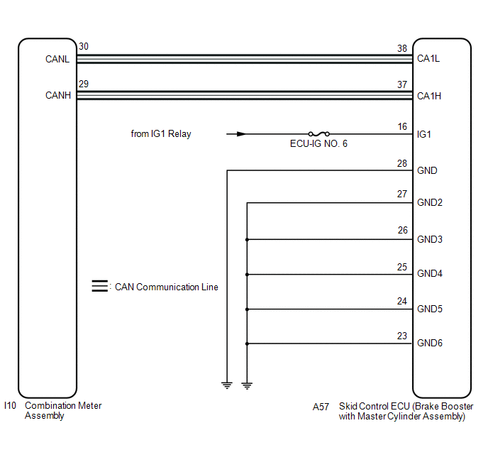
The skid control ECU (brake booster with master cylinder assembly) is connected to the combination meter assembly via CAN communication.
If any of the following is detected, the ABS warning light remains on:
- The skid control ECU (brake booster with master cylinder assembly) connector is disconnected from the brake booster with master cylinder assembly.
- There is a malfunction in the skid control ECU (brake booster with master cylinder assembly) internal circuit.
- There is an open in the wire harness between the combination meter assembly and the skid control ECU (brake booster with master cylinder assembly).
- The ABS control system is defective.
HINT:
In some cases, the Techstream cannot be used when the skid control ECU (brake booster with master cylinder assembly) is malfunctioning.
WIRING DIAGRAM
CAUTION / NOTICE / HINT
NOTICE:
-
When replacing the skid control ECU (brake booster with master cylinder assembly), perform initialization and calibration of the linear solenoid valve.
Click here
.gif)
- Inspect the fuses for circuits related to this system before performing the following procedure.
PROCEDURE
| 1. | CHECK CAN COMMUNICATION SYSTEM |
(a) Check if CAN communication system DTCs are output.
Click here
| Result | Proceed to |
|---|---|
| DTCs are not output. | A |
| DTCs are output. | B |
| B | .gif) | INSPECT CAN COMMUNICATION SYSTEM |
|
.gif)
| 2. | CHECK IF BRAKE BOOSTER WITH MASTER CYLINDER ASSEMBLY CONNECTOR IS SECURELY CONNECTED |
(a) Check if the skid control ECU (brake booster with master cylinder assembly) connector is securely connected.
OK:
The connector is securely connected.
| NG | | CONNECT CONNECTOR TO BRAKE BOOSTER WITH MASTER CYLINDER ASSEMBLY CORRECTLY |
|
| 3. | CHECK AUXILIARY BATTERY |
(a) Check the auxiliary battery voltage.
Standard Voltage:
| Tester Connection | Switch Condition | Specified Condition |
|---|---|---|
| Auxiliary battery | Power switch on (IG) | 11 to 14 V |
| Auxiliary battery | Power switch on (READY) | 11 to 15.5 V |
| NG | | CHARGE OR REPLACE AUXILIARY BATTERY |
|
| 4. | CHECK HARNESS AND CONNECTOR (IG1 TERMINAL) |
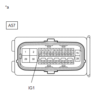
| (a) Disconnect the A57 skid control ECU (brake booster with master cylinder assembly) connector. |
|
(b) Turn the power switch on (IG).
(c) Measure the voltage according to the value(s) in the table below.
Standard Voltage:
| Tester Connection | Switch Condition | Specified Condition |
|---|---|---|
| A57-16 (IG1) - Body ground | Power switch on (IG) | 11 to 14 V |
| NG | | REPAIR OR REPLACE HARNESS OR CONNECTOR (IG1 CIRCUIT) |
|
| 5. | CHECK HARNESS AND CONNECTOR (GND TERMINAL) |
| (a) Turn the power switch off. |
|
.png)
(b) Measure the resistance according to the value(s) in the table below.
Standard Resistance:
| Tester Connection | Condition | Specified Condition |
|---|---|---|
| A57-28 (GND) - Body ground | Always | Below 1 Ω |
| A57-27 (GND2) - Body ground | Always | Below 1 Ω |
| A57-26 (GND3) - Body ground | Always | Below 1 Ω |
| A57-25 (GND4) - Body ground | Always | Below 1 Ω |
| A57-24 (GND5) - Body ground | Always | Below 1 Ω |
| A57-23 (GND6) - Body ground | Always | Below 1 Ω |
| NG | | REPAIR OR REPLACE HARNESS OR CONNECTOR (GND CIRCUIT) |
|
| 6. | READ VALUE USING TECHSTREAM (ABS WARNING LIGHT) |
(a) Reconnect the A57 skid control ECU (brake booster with master cylinder assembly) connector.
(b) Connect the Techstream to the DLC3.
(c) Turn the power switch on (IG).
(d) Select the Data List on the Techstream.
Click here
| Tester Display | Measurement Item | Range | Normal Condition | Diagnostic Note |
|---|---|---|---|---|
| ABS Warning Light | ABS warning light | ON or OFF | ON: Warning light on OFF: Warning light off | - |
| Tester Display |
|---|
| ABS Warning Light |
(e) Check the Techstream display condition of the ABS warning light.
| Result | Proceed to |
|---|---|
| Display of the Data List remains OFF. | A |
| Display of the Data List remains ON. | B |
| A | | INSPECT METER / GAUGE SYSTEM |
| B | | REPLACE BRAKE BOOSTER WITH MASTER CYLINDER ASSEMBLY |
READ NEXT:
 ABS Warning Light does not Come ON
DESCRIPTION The skid control ECU (brake booster with master cylinder assembly) is connected to the combination meter assembly via CAN communication. CAUTION / NOTICE / HINT NOTICE: When replacing the
Brake Warning Light Remains ON
DESCRIPTION The skid control ECU (brake booster with master cylinder assembly) is connected to the combination meter assembly via CAN communication. If any of the following is detected, the brake warn
Brake Warning Light does not Come ON
DESCRIPTION The skid control ECU (brake booster with master cylinder assembly) is connected to the combination meter assembly via CAN communication. CAUTION / NOTICE / HINT NOTICE: When replacing the
SEE MORE:
Problem Symptoms Table
PROBLEM SYMPTOMS TABLE HINT:
Use the table below to help determine the cause of problem symptoms. If multiple suspected areas are listed, the potential causes of the symptom are listed in order of probability in the "Suspected Area" column of the table. Check each symptom by checking the suspecte
Terminals Of Ecu
TERMINALS OF ECU *A w/ Manual (SOS) Switch - - Terminal No. (Symbol) Wiring Color Terminal Description Condition Specified Condition
*1: w/ Manual (SOS) Switch
*2: w/o Manual (SOS) Switch #: There is no wire color information I151-1 (GND1) - Body ground W-B - Body g
