Lexus NX: Terminals Of Ecu
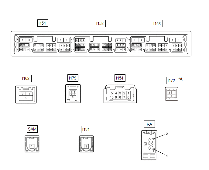
TERMINALS OF ECU
| *A | w/ Manual (SOS) Switch | - | - |
| Terminal No. (Symbol) | Wiring Color | Terminal Description | Condition | Specified Condition |
|---|---|---|---|---|
|
*1: w/ Manual (SOS) Switch
*2: w/o Manual (SOS) Switch #: There is no wire color information | ||||
| I151-1 (GND1) - Body ground | W-B - Body ground | Ground | Always | Below 1 Ω |
| I151-2 (GND2) - Body ground | B - Body ground | Ground | Always | Below 1 Ω |
| I151-3 (+B) - I151-1 (GND1) | R - W-B | Power source (+B) | Power switch off | 11 to 14 V |
| I151-4 (+B1) - I151-1 (GND1) | B - W-B | Power source (+B) | Power switch off | 11 to 14 V |
| I151-5 (TX1+) | B | AVC-LAN communication signal | - | - |
| I151-6 (TX1-) | P | AVC-LAN communication signal | - | - |
| I151-10 (AGND) - I151-1 (GND1) | Shielded - W-B | Shield ground | Always | Below 1 Ω |
| I151-11 (VAL+) - I151-13 (VA-) | B - R | Sound signal (Left) | External device system playing (when No. 1 stereo jack adapter assembly used) | A waveform synchronized with sound signals is output |
| I151-12 (VAR+) - I151-13 (VA-) | W - R | Sound signal (Right) | External device system playing (when No. 1 stereo jack adapter assembly used) | A waveform synchronized with sound signals is output |
| I151-13 (VA-) - I151-1 (GND1) | R - W-B | Sound signal ground | Always | Below 1 Ω |
| I151-14 (ADPG) - I151-13 (VA-) | L - R | External device connection detection signal | External device connected | 1.3 to 1.8 V |
| External device not connected | 2.2 to 3.3 V | |||
| I151-15 (ACC1) - I151-1 (GND1) | GR - W-B | Power source (ACC) | Power switch on (ACC) | 11 to 14 V |
| Power switch off | Below 1 V | |||
| I151-16 (ACC) - I151-1 (GND1) | Y - W-B | Power source (ACC) | Power switch on (ACC) | 11 to 14 V |
| Power switch off | Below 1 V | |||
| I151-17 (TX2+) | R | AVC-LAN communication signal | - | - |
| I151-18 (TX2-) | L | AVC-LAN communication signal | - | - |
| I151-21 (SW1) - I151-24 (SWG) | P - BR | Steering pad switch signal | No switch pushed | 2.97 to 3.56 V |
| Seek+ switch pushed | 0.27 to 0.35 V | |||
| Seek- switch pushed | 0.86 to 1.03 V | |||
| Vol+ switch pushed | 1.51 to 1.79 V | |||
| Vol- switch pushed | 2.22 to 2.66 V | |||
| I151-22 (SW2) - I151-24 (SWG) | R - BR | Steering pad switch signal | No switch pushed | 2.97 to 3.56 V |
| MODE switch pushed | 0.27 to 0.35 V | |||
| On hook switch pushed | 0.86 to 1.03 V | |||
| Off hook switch pushed | 1.51 to 1.79 V | |||
| Voice switch pushed | 2.22 to 2.66 V | |||
| I151-24 (SWG) - Body ground | BR - Body ground | Steering pad switch signal | Always | Below 1 Ω |
| I151-25 (MUT1) - Body ground | P - Body ground | Mute signal | Audio system playing | 2.0 V or higher |
| Audio system changing modes | Below 1 V | |||
| I151-27 (SPD) - I151-1 (GND1) | W - W-B | Vehicle speed signal | See "Vehicle Signal Check Mode" in Operation Check | - |
| I153-10 (USBV) - I151-1 (GND1)*1 | G - W-B | DCM (telematics transceiver) power supply | Power switch off | Below 1 V |
| Power switch on (ACC) | 4.75 to 5.25 V | |||
| I153-11 (USBG) - Body ground*1 | P - Body ground | Ground | Always | Below 1 Ω |
| I153-12 (SGND) - Body ground*1 | Shielded - Body ground | Shield ground | Always | Below 1 Ω |
| I153-13 (VOR+) - I151-1 (GND1)*1 | R - W-B | Receive voice signal | Destination assist service in use and operator speaking to vehicle occupant | A waveform synchronized with the received voice is output. |
| I153-14 (VOR-) - I151-1 (GND1)*1 | G - W-B | Receive voice signal | Destination assist service in use and operator speaking to vehicle occupant | A waveform synchronized with the received voice is output. |
| I153-15 (VOT+) - I151-1 (GND1)*1 | B - W-B | Sent voice signal | Destination assist service in use and vehicle occupant speaking to operator | A waveform synchronized with the sent voice is output. |
| I153-16 (VOT-) - I151-1 (GND1)*1 | W - W-B | Sent voice signal | Destination assist service in use and vehicle occupant speaking to operator | A waveform synchronized with the sent voice is output. |
| I152-1 (VMTF) - I151-1 (GND1) | V - W-B | Visual mute signal | Power switch on (ACC) Screen display changing | 3.5 V or higher → Below 1 V → 3.5 V or higher |
| I152-5 (CNH1) | L | Local bus communication signal | - | - |
| I152-6 (CNL1) | W | Local bus communication signal | - | - |
| I152-13 (CANH) | B | CAN communication signal | - | - |
| I152-14 (CANL) | W | CAN communication signal | - | - |
| I152-15 (ILL+) - I151-1 (GND1) | L - W-B | Illumination signal | Power switch on (IG), Light control switch in tail or head position | Below 1 V → 11 to 14 V |
| I152-16 (ILL-) - I151-1 (GND1) | V - W-B | Illumination signal | Power switch on (IG), light control switch off → tail or head position (Light intensity is not max or min.) | Below 1 V → Pulse generation |
| I152-19 (IG) - I151-1 (GND1) | P - W-B | Power source (IG) | Power switch off | Below 1 V |
| Power switch on (IG) | 11 to 14 V | |||
| I152-21 (MIN+) - I151-1 (GND1) | W - W-B | Microphone voice signal | See "Check Microphone" in Operation Check | - |
| I152-22 (MIN-) - I151-1 (GND1) | R - W-B | Microphone voice signal | See "Check Microphone" in Operation Check | - |
| I152-23 (MACC) - I151-1 (GND1)*2 | B - W-B | Telephone microphone assembly power supply | Power switch off | Below 1 V |
| Power switch on (ACC) | 4 to 6 V | |||
| I152-24 (SGND) - Body ground | Shielded - Body ground | Shield ground | Always | Below 1 Ω |
| I152-25 (SNS2) - I151-1 (GND1) | P - W-B | Microphone connection detection signal | Always | Below 1 V |
| I154-1 (FR+) - I151-1 (GND1) | G - W-B | Sound signal (Right) | Audio system playing | A waveform synchronized with sound is output |
| I154-2 (FL+) - I151-1 (GND1) | W - W-B | Sound signal (Left) | Audio system playing | A waveform synchronized with sound is output |
| I154-3 (RL+) - I151-1 (GND1) | G - W-B | Voice signal | Voice guidance sounding | A waveform synchronized with voice signals is output |
| I154-6 (FR-) - I151-1 (GND1) | B - W-B | Sound signal (Right) | Audio system playing | A waveform synchronized with sound is output |
| I154-7 (FL-) - I151-1 (GND1) | R - W-B | Sound signal (Left) | Audio system playing | A waveform synchronized with sound is output |
| I154-8 (RL-) - I151-1 (GND1) | R - W-B | Voice signal | Voice guidance sounding | A waveform synchronized with voice signals is output |
| I162-1 (GVI-) | # | Video signal (Digital) | - | - |
| I162-2 (GVI+) | # | Video signal (Digital) | - | - |
| I162-3 (GVG1) - Body ground | Shielded - Body ground | Shield ground | Always | Below 1 Ω |
| I179-1 (USV1) | # | Power source | - | - |
| I179-2 (US1-) | # | Data signal | - | - |
| I179-3 (US1+) | # | Data signal | - | - |
| I179-4 (UGD1) | # | Ground | - | - |
| I179-5 (USG1) - Body ground | Shielded - Body ground | Shield ground | Always | Below 1 Ω |
| I172-1 (USB+)*1 | # | Data signal | - | - |
| I172-2 (USB-)*1 | # | Data signal | - | - |
| I172-3 (USBS)*1 | Shielded | Ground | - | - |
| I181-1 (GPS) | #*1 B*2 | GPS signal | - | - |
| RA-5 - I151-1 (GND1) | # - W-B | Power source of antenna | Power switch on (ACC) Radio switch on and AM or FM selected | 11 to 14 V |
RADIO RECEIVER ASSEMBLY
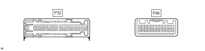
STEREO COMPONENT AMPLIFIER ASSEMBLY
| Terminal No. (Symbol) | Wiring Color | Terminal Description | Condition | Specified Condition |
|---|---|---|---|---|
| *: w/ Manual (SOS) Switch | ||||
| P32-3 (GND) - Body ground | W-B - Body ground | Ground | Always | Below 1 Ω |
| P32-4 (WFL+) - P32-3 (GND) | B - W-B | Sound signal (Front Left) | Audio system playing | A waveform synchronized with sound signals is output |
| P32-5 (WFR+) - P32-3 (GND) | W - W-B | Sound signal (Front Right) | Audio system playing | A waveform synchronized with sound signals is output |
| P32-8 (RL+) - P32-3 (GND) | R - W-B | Sound signal (Rear Left) | Audio system playing | A waveform synchronized with sound signals is output |
| P32-9 (RR+) - P32-3 (GND) | B - W-B | Sound signal (Rear Right) | Audio system playing | A waveform synchronized with sound signals is output |
| P32-12 (FL+) - P32-3 (GND) | P - W-B | Sound signal (Front Left) | Audio system playing | A waveform synchronized with sound signals is output |
| P32-13 (FR+) - P32-3 (GND) | P - W-B | Sound signal (Front Right) | Audio system playing | A waveform synchronized with sound signals is output |
| P32-16 (+B2) - P32-3 (GND) | B - W-B | Power source (+B) | Power switch off | 11 to 14 V |
| P32-18 (GND2) - Body ground | W-B - Body ground | Ground | Always | Below 1 Ω |
| P32-19 (WFL-) - P32-3 (GND) | Y - W-B | Sound signal (Front Left) | Audio system playing | A waveform synchronized with sound signals is output |
| P32-20 (WFR-) - P32-3 (GND) | R - W-B | Sound signal (Front Right) | Audio system playing | A waveform synchronized with sound signals is output |
| P32-23 (RL-) - P32-3 (GND) | W - W-B | Sound signal (Rear Left) | Audio system playing | A waveform synchronized with sound signals is output |
| P32-24 (RR-) - P32-3 (GND) | G - W-B | Sound signal (Rear Right) | Audio system playing | A waveform synchronized with sound signals is output |
| P32-27 (FL-) - P32-3 (GND) | V - W-B | Sound signal (Front Left) | Audio system playing | A waveform synchronized with sound signals is output |
| P32-28 (FR-) - P32-3 (GND) | R - W-B | Sound signal (Front Right) | Audio system playing | A waveform synchronized with sound signals is output |
| P46-1 (MUTE) - P32-3 (GND) | P - W-B | Mute signal | Power switch on (ACC), audio system playing | 2.0 V or higher |
| Audio system changing modes | Below 1 V | |||
| P46-2 (L-) - P32-3 (GND) | R - W-B | Sound signal (Left) | Audio system playing | A waveform synchronized with sound signals is output |
| P46-3 (L+) - P32-3 (GND) | W - W-B | Sound signal (Left) | Audio system playing | A waveform synchronized with sound signals is output |
| P46-4 (R-) - P32-3 (GND) | B - W-B | Sound signal (Right) | Audio system playing | A waveform synchronized with sound signals is output |
| P46-5 (R+) - P32-3 (GND) | G - W-B | Sound signal (Right) | Audio system playing | A waveform synchronized with sound signals is output |
| P46-6 (SLD) - Body ground | Shielded - Body ground | Shielded ground | Always | Below 1 Ω |
| P46-7 (TX-) | L | AVC-LAN communication signal | - | - |
| P46-8 (TX+) | R | AVC-LAN communication signal | - | - |
| P46-11 (SPD) - P32-3 (GND) | V - W-B | Vehicle speed signal | Power switch on (IG), wheel being rotated | Pulse generation |
| P46-12 (ACC) - P32-3 (GND) | P - W-B | Power source (ACC) | Power switch off | Below 1 V |
| Power switch on (ACC) | 11 to 14 V | |||
| P46-14 (II1-) - P32-3 (GND) | R - W-B | Voice signal | Voice guidance sounding | A waveform synchronized with voice signals is output |
| P46-15 (II1+) - P32-3 (GND) | G - W-B | Voice signal | Voice guidance sounding | A waveform synchronized with voice signals is output |
| P46-18 (SLD1) - Body ground | Shielded - Body ground | Shielded ground | Always | Below 1 Ω |
| P46-24 (TMUT) - P32-3 (GND)* | B - W-B | Mute signal | Power switch on (ACC), audio system playing | 2.0 V or higher |
| Audio system changing modes | Below 1 V | |||
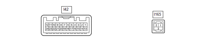
MULTI-DISPLAY ASSEMBLY
 -
-
| Terminal No. (Symbol) | Wiring Color | Terminal Description | Condition | Specified Condition |
|---|---|---|---|---|
| #: There is no wire color information | ||||
| I42-2 (ILL) - I42-13 (GND1) | LG - W-B | Illumination signal | Power switch on (IG), light control switch off → tail or head position | Below 1 V → 11 to 14 V |
| I42-3 (REV) - I42-13(GND1) | R - W-B | Reverse signal | Power switch on (READY), shift position not in R → in R | 2 V or less → 11 to 14 V |
| I42-7 (TX+) | B | AVC-LAN communication signal | - | - |
| I42-8 (V+) - I42-9 (V-) | W - R | Video signal | Power switch on (READY) Shift position in R Camera lens not covered, displaying image | Pulse generation (Refer to waveform 1) |
| Power switch on (READY) Shift position in R Camera lens covered, blacking out screen | Pulse generation (Refer to waveform 2) | |||
| I42-9 (V-) - Body ground | R - Body ground | Video signal ground | Always | Below 1 Ω |
| I42-10 (CA+) - I42-21 (CGND) | B - G | Power source | Power switch on (ACC) | 5.5 to 7.05 V |
| I42-11 (VMTI) - I42-13 (GND1) | V - W-B | Visual mute signal | When image on display switches | 3.5 V or higher → Below 1 V → 3.5 V or higher |
| I42-12 (B) - I42-13 (GND1) | BE - W-B | Power source (+B) | Power switch off | 11 to 14 V |
| I42-13 (GND1) - Body ground | W-B - Body ground | Ground | Always | Below 1 Ω |
| I42-19 (TX-) | P | AVC-LAN communication signal | - | - |
| I42-20 (CSLD) - Body ground | Shielded - Body ground | Shield ground | Always | Below 1 Ω |
| I42-21 (CGND) - Body ground | G - Body ground | Camera ground | Always | Below 1 Ω |
| I42-24 (ACC) - I42-13 (GND1) | Y - W-B | Power source (ACC) | Power switch on (ACC) | 11 to 14 V |
| Power switch off | Below 1 Ω | |||
| I165-1 (GV+) | # | Video signal (Digital) | - | - |
| I165-2 (GV-) | # | Video signal (Digital) | - | - |
| I165-3 (GVG) | Shielded | Shield ground | - | - |
(a) Reference (Oscilloscope waveform):
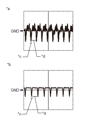
| *a | Waveform 1 (camera lens not covered, displaying image) |
| *b | Waveform 2 (camera lens covered, blacking out screen) |
| *c | Synchronization Signal |
| *d | Video Waveform |
(1) Waveform 1 (camera lens is not covered, displaying an image)
| Item | Content |
|---|---|
| Measurement terminal | I42-8 (V+) - I42-9 (V-) |
| Measurement setting | 200 mV/DIV., 50 μs./DIV. |
| Condition | Power switch on (READY), shift position in R, camera lens not covered, displaying image |
HINT:
- The video waveform changes according to the image sent by the television camera assembly.
- The video waveform is constantly output when the power switch is on (ACC).
(2) Waveform 2 (camera lens is covered, blacking out the screen)
| Item | Content |
|---|---|
| Measurement terminal | I42-8 (V+) - I42-9 (V-) |
| Measurement setting | 200 mV/DIV., 50 μs./DIV. |
| Condition | Power switch on (READY), shift position in R, camera lens covered, blacking out screen |
HINT:
- The video waveform changes according to the image sent by the television camera assembly.
- The video waveform is constantly output when the power switch is on (ACC).
REMOTE OPERATION CONTROLLER ASSEMBLY (REMOTE TOUCH)

| Terminal No. (Symbol) | Wiring Color | Terminal Description | Condition | Specified Condition |
|---|---|---|---|---|
| I71-1 (+B) - I71-10 (GND) | W - LA | Power source (+B) | Power switch off | 11 to 14 V |
| I71-6 (ACC) - I71-10 (GND) | LG - LA | Power source (ACC) | Power switch on (ACC) | 11 to 14 V |
| Power switch off | Below 1 V | |||
| I71-8 (MO-) | W | Local bus communication signal | - | - |
| I71-9 (MO+) | L | Local bus communication signal | - | - |
| I71-2 (ILL+) - I71-10 (GND) | SB - LA | Illumination signal | Power switch on (IG), light control switch off → tail or head position | Below 1 V → 11 to 14 V |
| I71-10 (GND) - Body ground | LA - Body ground | Ground | Always | Below 1 Ω |
| I71-5 (ILL-) - I71-10 (GND) | L - LA | Illumination signal | Power switch on (IG), light control switch off → tail or head position (Light intensity is not max or min.) | Below 1 V → Pulse generation |
DCM (TELEMATICS TRANSCEIVER) (w/ Manual [SOS] Switch)
Click here .gif)
CLOCK ASSEMBLY
Click here
READ NEXT:
 Dtc Check / Clear
DTC CHECK / CLEAR CHECK DTC (CHECK USING Techstream) (a) Connect the Techstream to the DLC3. (b) Turn the power switch on (IG) and wait for 90 seconds. (c) Turn the Techstream on. (d) Enter the follow
Freeze Frame Data
FREEZE FRAME DATA CHECK FREEZE FRAME DATA (a) Connect the Techstream to the DLC3. (b) Turn the power switch on (IG). (c) Turn the Techstream on. (d) Enter the following menus: Body Electrical / Naviga
Data List / Active Test
DATA LIST / ACTIVE TEST DATA LIST NOTICE: In the table below, the values listed under "Normal Condition" are reference values. Do not depend solely on these reference values when deciding whether a pa
SEE MORE:
Voice Guidance Circuit between Radio Receiver and Stereo Component Amplifier
DESCRIPTION This circuit is used when the voice switch of the steering pad switch assembly is pushed. Using this circuit, the radio and display receiver assembly sends signals to the stereo component amplifier assembly. WIRING DIAGRAM PROCEDURE 1. CHECK HARNESS AND CONNECTOR (RADIO RECEIVER A
Installation
INSTALLATION PROCEDURE 1. INSTALL RAIN SENSOR TAPE NOTICE: The rain sensor tape is reusable. Only replace the tape if it is damaged or contaminated. (a) Clean the rain sensor sensing portion with a piece of cloth, etc. (b) Peel off the smaller release sheet, and then attach the rain sensor tape o
