Lexus NX: Accelerator Pedal Sensor
Components
COMPONENTS
ILLUSTRATION
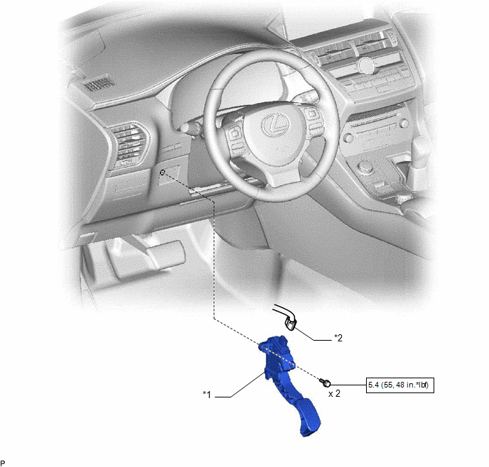
| *1 | ACCELERATOR PEDAL SENSOR ASSEMBLY | *2 | ACCELERATOR PEDAL SENSOR CONNECTOR |
.png) | N*m (kgf*cm, ft.*lbf): Specified torque | - | - |
On-vehicle Inspection
ON-VEHICLE INSPECTION
PROCEDURE
1. INSPECT ACCELERATOR PEDAL SENSOR ASSEMBLY
(a) Connect the Techstream to the DLC3.
(b) Turn the power switch on (IG).
(c) Turn the Techstream on.
(d) Enter the following menus: Powertrain / Hybrid Control / Data List / Accel Pedal Pos #1, Accel Pedal Pos #2.
Powertrain > Hybrid Control > Data List| Tester Display |
|---|
| Accel Pedal Pos #1 |
| Accel Pedal Pos #2 |
(e) Operate the accelerator pedal sensor assembly and check that the "Accel Pedal Pos #1, Accel Pedal Pos #2" values are within the specification.
Standard (Accel Pedal Pos #1):
| Accelerator Pedal Condition | Specified Condition |
|---|---|
| Released | 10 to 22% |
| Depressed | 52 to 90% |
Standard (Accel Pedal Pos #2):
| Accelerator Pedal Condition | Specified Condition |
|---|---|
| Released | 24 to 40% |
| Depressed | 68 to 95% |
If the result is not as specified, check the accelerator pedal sensor assembly, wire harness or ECM.
Removal
REMOVAL
PROCEDURE
1. REMOVE ACCELERATOR PEDAL SENSOR ASSEMBLY
NOTICE:
This accelerator pedal does not require lubrication.
Do not apply oil or other lubrication to the accelerator pedal sensor assembly.
If applied, the accelerator pedal sensor assembly must be replaced.
| (a) Disconnect the accelerator pedal sensor assembly connector. |
|
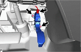
(b) Remove the 2 bolts and accelerator pedal sensor assembly.
NOTICE:
- Avoid physical shocks to the accelerator pedal sensor assembly.
- Do not disassemble the accelerator pedal sensor assembly.
Installation
INSTALLATION
PROCEDURE
1. INSTALL ACCELERATOR PEDAL SENSOR ASSEMBLY
NOTICE:
This accelerator pedal does not require lubrication.
Do not apply oil or other lubrication to the accelerator pedal sensor assembly.
If applied, the accelerator pedal sensor assembly must be replaced.
(a) Install the accelerator pedal sensor assembly with the 2 bolts.
Torque:
5.4 N·m {55 kgf·cm, 48 in·lbf}
NOTICE:
- Avoid physical shocks to the accelerator pedal sensor assembly.
- Do not disassemble the accelerator pedal sensor assembly.
(b) Connect the accelerator pedal sensor assembly connector.
READ NEXT:
 Components
COMPONENTS ILLUSTRATION *1 TONNEAU COVER ASSEMBLY - - ILLUSTRATION *1 DECK BOARD ASSEMBLY *2 DECK FLOOR BOX LH *3 NO. 3 DECK BOARD SUB-ASSEMBLY - - ILLUSTRATION
Removal
REMOVAL PROCEDURE 1. PRECAUTION Click here 2. CHECK FOR DTC (a) Check for DTCs. Click here NOTICE: Confirm that P0AA6 (Hybrid Battery Voltage System Isolation Fault) is not output before removing
SEE MORE:
On-vehicle Inspection
ON-VEHICLE INSPECTION CAUTION / NOTICE / HINT NOTICE: If using a dropper to adjust the fluid amount, make sure that the dropper has not been used with mineral oils, water or deteriorated brake fluid. Sealed areas may deteriorate and lead to fluid leaks, or the fluid may deteriorate and lead to decre
Satellite Radio Broadcast cannot be Selected or After Selecting Broadcast, Broadcast cannot be Added into Memory
CAUTION / NOTICE / HINT NOTICE:
Some satellite radio broadcasts require payment. A contract must be made between a satellite radio company and the user. If the contract expires, it will not be possible to listen to the broadcast.
When replacing the radio receiver assembly, always replace it wit
