Lexus NX: Adjustment
ADJUSTMENT
PROCEDURE
1. INSPECT SHIFT LEVER POSITION SENSOR POSITION
(a) Apply the parking brake.
(b) Lock the wheels with chocks to secure the vehicle.
(c) Turn the power switch on (READY).
(d) Move the shift lever to D and release the brake.
NOTICE:
Be sure to apply the parking brake and lock the wheels with chocks to secure the vehicle.
| (e) Slowly move the shift lever to N and measure moving distance (A) of the shift lever from the original point to the gear disengagement point. NOTICE: Be sure to move the shift lever slowly. |
|
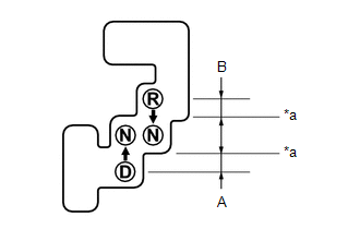
(f) Move the shift lever to R and release the brake.
NOTICE:
Be sure to apply the parking brake and lock the wheels with chocks to secure the vehicle.
(g) Slowly move the shift lever to N and measure moving distance (B) of the shift lever from the original point to the gear disengagement point.
NOTICE:
Be sure to move the shift lever slowly.
(h) Check that moving distances (A) and (B) shown in the illustration are almost the same.
HINT:
- If moving distances (A) and (B) are almost the same, adjustment of the shift lever position is not necessary.
- If moving distance (A) is shorter than (B), perform adjustment of the shift lever position [*1].
- If moving distance (B) is shorter than (A), perform adjustment of the shift lever position [*2].
2. ADJUST SHIFT LEVER POSITION SENSOR POSITION
(a) If moving distance (A) is shorter than (B). [*1]
HINT:
If the shift lever is moved from R to N, the moving distance of the shift lever from the original point to the gear disengagement point becomes longer.
(1) Move the shift lever to N.
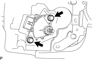
| (2) Loosen the 2 bolts. |
|
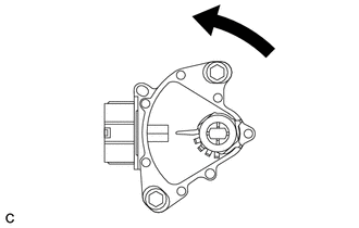
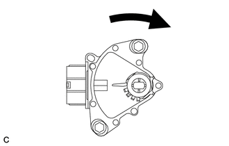
| (3) Slightly turn the shift lever position sensor counterclockwise. |
|
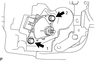
| (4) Tighten the 2 bolts in the order shown in the illustration. Torque: 13 N·m {133 kgf·cm, 10 ft·lbf} |
|
(5) Recheck the shift lever position sensor.
(b) If moving distance (B) is shorter than (A). [*2]
HINT:
If the shift lever is moved from D to N, the moving distance of the shift lever from the original point to the gear disengagement point becomes longer.
(1) Move the shift lever to N.
| (2) Loosen the 2 bolts. |
|
| (3) Slightly turn the shift lever position sensor clockwise. |
|
| (4) Tighten the 2 bolts in the order shown in the illustration. Torque: 13 N·m {133 kgf·cm, 10 ft·lbf} |
|
(5) Recheck the shift lever position sensor.
READ NEXT:
 Installation
INSTALLATION PROCEDURE 1. INSTALL SHIFT LEVER POSITION SENSOR (a) Install the shift lever position sensor to the manual valve shaft. (b) Temporarily install the 2 bolts. (c) Install the lock plate and
Components
COMPONENTS ILLUSTRATION *1 CRUISE CONTROL MAIN SWITCH *2 SHIFT PADDLE SWITCH LH (TRANSMISSION SHIFT SWITCH ASSEMBLY) *3 SHIFT PADDLE SWITCH RH (TRANSMISSION SHIFT SWITCH ASSEMBLY) *4
SEE MORE:
Zero Point Calibration of Yaw Rate Sensor undone (C1210,C1336)
DESCRIPTION The skid control ECU (brake booster with master cylinder assembly) receives signals from the yaw rate and acceleration sensor (airbag ECU assembly) via CAN communication. The airbag ECU assembly has a built-in yaw rate and acceleration sensor and detects the vehicle condition using 2 cir
Airbag ECU Malfunction (B1000)
DESCRIPTION The airbag ECU assembly consists of a deceleration sensor, safing sensor, drive circuit, diagnosis circuit, ignition control, etc. If the airbag ECU assembly receives signals from the deceleration sensor, it determines whether or not the SRS should be activated. DTC B1000 is stored when
