Lexus NX: Installation
INSTALLATION
PROCEDURE
1. INSTALL SHIFT LEVER POSITION SENSOR
(a) Install the shift lever position sensor to the manual valve shaft.
(b) Temporarily install the 2 bolts.
(c) Install the lock plate and tighten the lock nut.
Torque:
6.9 N·m {70 kgf·cm, 61 in·lbf}
(d) Temporarily install the control shaft lever to the manual valve shaft.
| (e) Turn the control shaft lever clockwise until it stops, and then turn it counterclockwise 2 notches. |
|
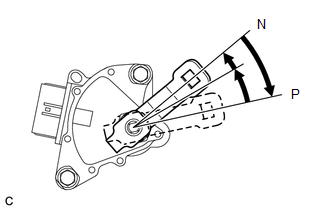
(f) Remove the control shaft lever from the manual valve shaft.
| (g) Align the protruding part with the neutral basic line. NOTICE: There is play in the nut stopper (protruding part). Position the protruding part so that it is aligned with the neutral basic line when it is in the center of its range of play. |
|
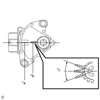
| (h) Tighten the 2 bolts in the order shown in the illustration. Torque: 13 N·m {133 kgf·cm, 10 ft·lbf} |
|
.png)
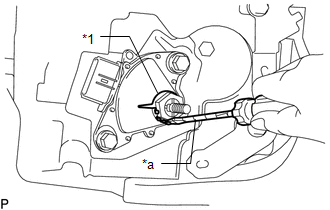
| (i) Using a screwdriver with its tip wrapped with protective tape, secure the lock nut with the lock plate. |
|
(j) Install the control shaft lever, washer, and nut to the manual valve shaft.
Torque:
12.7 N·m {130 kgf·cm, 9 ft·lbf}
(k) Connect the shift lever position sensor connector.
2. CONNECT TRANSMISSION CONTROL CABLE ASSEMBLY
(a) Move the shift lever to N.
| (b) Install a new clip to the No. 1 transmission control cable bracket. |
|
.png)
(c) Connect the transmission control cable assembly to the control shaft lever with the nut.
Torque:
12 N·m {122 kgf·cm, 9 ft·lbf}
3. INSPECT SHIFT LEVER POSITION SENSOR POSITION
Click here .gif)
4. ADJUST SHIFT LEVER POSITION SENSOR POSITION
Click here
5. INSPECT SHIFT LEVER POSITION
Click here
6. ADJUST SHIFT LEVER POSITION
Click here
7. INSTALL NO. 1 ENGINE UNDER COVER ASSEMBLY
Click here
READ NEXT:
 Components
COMPONENTS ILLUSTRATION *1 CRUISE CONTROL MAIN SWITCH *2 SHIFT PADDLE SWITCH LH (TRANSMISSION SHIFT SWITCH ASSEMBLY) *3 SHIFT PADDLE SWITCH RH (TRANSMISSION SHIFT SWITCH ASSEMBLY) *4
Removal
REMOVAL CAUTION / NOTICE / HINT NOTICE:
Do not replace the spiral cable with the battery connected and the power switch on (IG).
Do not rotate the spiral cable when the following conditions are m
SEE MORE:
Terminals Of Ecm
TERMINALS OF ECM HINT: The standard voltage, resistance and waveform between each pair of the ECM terminals is shown in the table below. The appropriate conditions for checking each pair of the terminals is also indicated. The result of checks should be compared with the standard voltage, resistanc
Components
COMPONENTS ILLUSTRATION *1 AIR CONDITIONER PRESSURE SENSOR - - N*m (kgf*cm, ft.*lbf): Specified torque ● Non-reusable part Compressor oil ND-OIL 11 or equivalent - -
