Lexus NX: AV Signal Stoppage (Low Battery Voltage) (B158F)
DESCRIPTION
This DTC is stored when a video or audio signal is interrupted due to auxiliary battery voltage input to the radio receiver assembly dropping temporarily.
| DTC No. | Detection Item | DTC Detection Condition | Trouble Area |
|---|---|---|---|
| B158F | AV Signal Stoppage (Low Battery Voltage) | A video or audio signal is interrupted when the auxiliary battery drops |
|
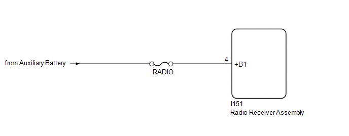
WIRING DIAGRAM
CAUTION / NOTICE / HINT
NOTICE:
- Inspect the fuse for circuits related to this system before performing the following procedure.
-
When replacing the radio receiver assembly, always replace it with a new one.
If a radio receiver assembly which was installed to another vehicle is used, the following may occur:
- A communication malfunction DTC may be stored.
- The radio receiver assembly may not operate normally.
HINT:
Depending on the parts that are replaced during vehicle inspection or maintenance, performing initialization, registration or calibration may be needed. Refer to Precaution for Audio and Visual System.
Click here .gif)
PROCEDURE
| 1. | CHECK VEHICLE SIGNAL (OPERATION CHECK) |
| (a) Enter the "Vehicle Signal Check Mode" screen. Refer to Check Vehicle Signal in Operation Check. Click here |
|
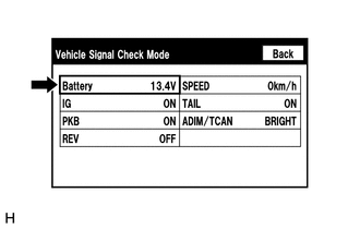
(b) Measure the auxiliary battery voltage.
Standard voltage:
11 to 14 V
HINT:
This display is updated once per second. As a result, it is normal for the display to lag behind the actual switch operation.
| NG | .gif) | GO TO STEP 3 |
|
.gif)
| 2. | CHECK DTC |
(a) Clear the DTCs.
Click here
(b) Recheck for DTCs and check that no DTCs are output.
Click here
OK:
No DTCs are output.
| OK | | USE SIMULATION METHOD TO CHECK |
| NG | | REPLACE RADIO RECEIVER ASSEMBLY |
| 3. | CHECK HARNESS AND CONNECTOR (RADIO RECEIVER ASSEMBLY - BATTERY) |
| (a) Disconnect the radio receiver assembly connector. |
|
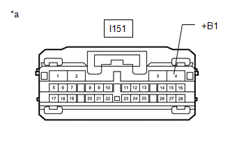
(b) Measure the voltage according to the value(s) in the table below.
Standard Voltage:
| Tester Connection | Condition | Specified Condition |
|---|---|---|
| I151-4 (+B1) - Body ground | Power switch off | 11 to 14 V |
| OK | | REPLACE RADIO RECEIVER ASSEMBLY |
| NG | | REPAIR OR REPLACE HARNESS OR CONNECTOR |
READ NEXT:
 Stereo Component Amplifier Malfunction (B15A3)
DESCRIPTION These DTCs are stored when a malfunction occurs in the stereo component amplifier assembly. DTC No. Detection Item DTC Detection Condition Trouble Area B15A3 Stereo Componen
Display Malfunction (B15A6,B15B0)
DESCRIPTION These DTCs are stored when a malfunction occurs in the multi-display assembly. DTC No. Detection Item DTC Detection Condition Trouble Area B15A6 Display Malfunction When o
Short in GPS Antenna (B15C0,B15C1)
DESCRIPTION These DTCs are stored when a malfunction occurs in the navigation antenna assembly. DTC No. Detection Item DTC Detection Condition Trouble Area B15C0 Short in GPS Antenna
SEE MORE:
Removal
REMOVAL PROCEDURE 1. REMOVE NO. 1 ENGINE UNDER COVER ASSEMBLY Click here 2. DRAIN COOLANT (for Inverter Coolant) Click here 3. REMOVE UPPER RADIATOR SUPPORT SUB-ASSEMBLY Click here 4. DISCONNECT NO. 2 INVERTER COOLING HOSE ASSEMBLY Click here 5. REMOVE WATER PUMP WITH MOTOR (a) Disconn
Operation Check
OPERATION CHECK CHECK POWER RETRACTABLE MIRROR FUNCTION (a) Turn the power switch on (ACC). (b) When the outer rear view mirror assembly LH and outer rear view mirror assembly RH are in the driving position, press the mirror retract switch in the outer mirror switch assembly and check that they move
