Lexus NX: Short in GPS Antenna (B15C0,B15C1)
DESCRIPTION
These DTCs are stored when a malfunction occurs in the navigation antenna assembly.
| DTC No. | Detection Item | DTC Detection Condition | Trouble Area |
|---|---|---|---|
| B15C0 | Short in GPS Antenna | Navigation antenna error |
|
| B15C1 | Open in GPS Antenna | Error of the power source to the navigation antenna |
|
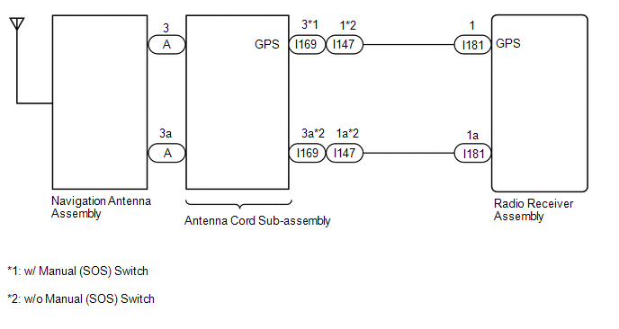
WIRING DIAGRAM
CAUTION / NOTICE / HINT
NOTICE:
When replacing the radio receiver assembly, always replace it with a new one.
If a radio receiver assembly which was installed to another vehicle is used, the following may occur:
- A communication malfunction DTC may be stored.
- The radio receiver assembly may not operate normally.
HINT:
Depending on the parts that are replaced during vehicle inspection or maintenance, performing initialization, registration or calibration may be needed. Refer to Precaution for Audio and Visual System.
Click here .gif)
PROCEDURE
| 1. | CHECK DTC |
(a) Clear the DTCs.
Click here
(b) Recheck for DTCs and check that no DTCs are output.
Click here
OK:
No DTCs are output.
| OK | .gif) | USE SIMULATION METHOD TO CHECK |
|
.gif)
| 2. | INSPECT NAVIGATION ANTENNA ASSEMBLY |
(a) Remove the navigation antenna assembly.
Click here
(b) Inspect the navigation antenna assembly.
Click here
| NG | | REPLACE NAVIGATION ANTENNA ASSEMBLY |
|
| 3. | CHECK VEHICLE TYPE |
(a) Check the vehicle type.
| Result | Proceed to |
|---|---|
| w/ Manual (SOS) Switch | A |
| w/o Manual (SOS) Switch | B |
| B | | GO TO STEP 6 |
|
| 4. | CHECK ANTENNA CORD SUB-ASSEMBLY |
| (a) Disconnect the antenna connector from the navigation antenna assembly. |
|
(b) Disconnect the antenna connector from the wire harness.
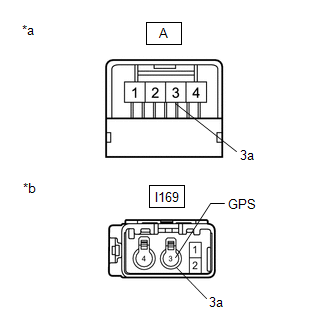
(c) Measure the resistance according to the value(s) in the table below.
Standard Resistance:
| Tester Connection | Condition | Specified Condition |
|---|---|---|
| A-3 - I169-3 (GPS) | Always | Below 1 Ω |
| A-3a - I169-3a | Always | Below 1 Ω |
| A-3 - Body ground | Always | 10 kΩ or higher |
| A-3a - Body ground | Always | 10 kΩ or higher |
| NG | | REPLACE ANTENNA CORD SUB-ASSEMBLY |
|
| 5. | CHECK HARNESS AND CONNECTOR (ANTENNA CORD SUB-ASSEMBLY - RADIO RECEIVER ASSEMBLY) |
| (a) Disconnect the antenna cord sub-assembly connector. |
|
(b) Disconnect the radio receiver assembly connector.
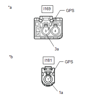
(c) Measure the resistance according to the value(s) in the table below.
Standard Resistance:
| Tester Connection | Condition | Specified Condition |
|---|---|---|
| I169-3 (GPS) - I181-1 (GPS) | Always | Below 1 Ω |
| I169-3a - I181-1a | Always | Below 1 Ω |
| I169-3 (GPS) - Body ground | Always | 10 kΩ or higher |
| I169-3a - Body ground | Always | 10 kΩ or higher |
| OK | | REPLACE RADIO RECEIVER ASSEMBLY |
| NG | | REPAIR OR REPLACE HARNESS OR CONNECTOR |
| 6. | CHECK ANTENNA CORD SUB-ASSEMBLY |
| (a) Disconnect the antenna connector from the navigation antenna assembly. |
|
(b) Disconnect the antenna connector from the wire harness.
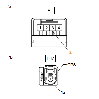
(c) Measure the resistance according to the value(s) in the table below.
Standard Resistance:
| Tester Connection | Condition | Specified Condition |
|---|---|---|
| A-3 - I147-1 (GPS) | Always | Below 1 Ω |
| A-3a - I147-1a | Always | Below 1 Ω |
| A-3 - Body ground | Always | 10 kΩ or higher |
| A-3a - Body ground | Always | 10 kΩ or higher |
| NG | | REPLACE ANTENNA CORD SUB-ASSEMBLY |
|
| 7. | CHECK HARNESS AND CONNECTOR (ANTENNA CORD SUB-ASSEMBLY - RADIO RECEIVER ASSEMBLY) |
| (a) Disconnect the antenna cord sub-assembly connector. |
|
(b) Disconnect the radio receiver assembly connector.
(c) Measure the resistance according to the value(s) in the table below.
Standard Resistance:
| Tester Connection | Condition | Specified Condition |
|---|---|---|
| I147-1 (GPS) - I181-1 (GPS) | Always | Below 1 Ω |
| I147-1a - I181-1a | Always | Below 1 Ω |
| I147-1 (GPS) - Body ground | Always | 10 kΩ or higher |
| I147-1a - Body ground | Always | 10 kΩ or higher |
| OK | | REPLACE RADIO RECEIVER ASSEMBLY |
| NG | | REPAIR OR REPLACE HARNESS OR CONNECTOR |
READ NEXT:
 Speaker Output Short (B15C3)
DESCRIPTION This DTC is stored when a malfunction occurs in the speakers. In addition, the radio receiver assembly detects a malfunction via the stereo component amplifier assembly. DTC No. Detec
Stereo Component Amplifier Disconnected (B15D3)
DESCRIPTION The radio receiver assembly and stereo component amplifier assembly are connected by the AVC-LAN communication line. This DTC is stored when an AVC-LAN communication error occurs between t
Display Disconnected (B15D6)
DESCRIPTION The multi-display assembly and radio receiver assembly are connected by the AVC-LAN communication line. This DTC is stored when an AVC-LAN communication error occurs between the multi-disp
SEE MORE:
Problem Symptoms Table
PROBLEM SYMPTOMS TABLE HINT:
Use the table below to help determine the cause of problem symptoms. If multiple suspected areas are listed, the potential causes of the symptoms are listed in order of probability in the "Suspected Area" column of the table. Check each symptom by checking the suspect
Installation
INSTALLATION PROCEDURE 1. INSTALL CAMSHAFT TIMING OIL CONTROL VALVE ASSEMBLY (a) Apply a light coat of engine oil to a new O-ring and install the O-ring to the camshaft timing oil control valve assembly. NOTICE: Do not damage the O-ring when installing. HINT: An O-ring is already installed in a new
