Lexus NX: AVC-LAN Circuit
DESCRIPTION
Each audio system component connected to the AVC-LAN (communication bus) transfers switch signals using the audio visual communication local area network.
If a short to +B or short to ground occurs in the AVC-LAN, the audio system will not function normally because communication is not possible.
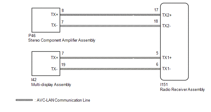
WIRING DIAGRAM
CAUTION / NOTICE / HINT
NOTICE:
When replacing the radio receiver assembly, always replace it with a new one.
If a radio receiver assembly which was installed to another vehicle is used, the following may occur:
- A communication malfunction DTC may be stored.
- The radio receiver assembly may not operate normally.
HINT:
Depending on the parts that are replaced during vehicle inspection or maintenance, performing initialization, registration or calibration may be needed. Refer to Precaution for Audio and Visual System.
Click here .gif)
PROCEDURE
| 1. | INSPECT RADIO RECEIVER ASSEMBLY |
(a) Remove the radio receiver assembly.
Click here
| (b) Measure the resistance according to the value(s) in the table below. Standard Resistance:
|
|
| NG | .gif) | REPLACE RADIO RECEIVER ASSEMBLY |
|
.gif)
| 2. | CHECK HARNESS AND CONNECTOR (AVC-LAN CIRCUIT) |
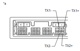
(a) Disconnect the I151 radio receiver assembly connector.
(b) Disconnect the P46 stereo component amplifier assembly connector.
(c) Disconnect the I42 multi-display assembly connector.
(d) Measure the resistance according to the value(s) in the table below.
Standard Resistance:
| Tester Connection | Condition | Specified Condition |
|---|---|---|
| I151-17 (TX2+) - P46-8 (TX+) | Always | Below 1 Ω |
| I151-18 (TX2-) - P46-7 (TX-) | Always | Below 1 Ω |
| I151-5 (TX1+) - I42-7 (TX+) | Always | Below 1 Ω |
| I151-6 (TX1-) - I42-19 (TX-) | Always | Below 1 Ω |
| I151-17 (TX2+) - Body ground | Always | 10 kΩ or higher |
| I151-18 (TX2-) - Body ground | Always | 10 kΩ or higher |
| I151-5 (TX1+) - Body ground | Always | 10 kΩ or higher |
| I151-6 (TX1-) - Body ground | Always | 10 kΩ or higher |
| NG | | REPAIR OR REPLACE HARNESS OR CONNECTOR |
|
| 3. | INSPECT MALFUNCTIONING PARTS |
(a) Disconnect and reconnect each slave unit one by one until the master unit returns to normal operation.
HINT:
- Check all slave units.
- When disconnecting a slave unit causes the master unit to return to normal operation, this indicates that the slave unit is malfunctioning. Replace the malfunctioning slave unit.
OK:
Master unit returns to normal operation.
| OK | | REPLACE MALFUNCTIONING PARTS |
| NG | | REPLACE RADIO RECEIVER ASSEMBLY |
READ NEXT:
 Vehicle Speed Signal Circuit between Stereo Component Amplifier and Combination Meter
DESCRIPTION The stereo component amplifier assembly receives a vehicle speed signal from the combination meter assembly to control the ASL function. HINT:
A voltage of 12 V or 5 V is output from ea
Voice Guidance Circuit between Radio Receiver and Stereo Component Amplifier
DESCRIPTION This circuit is used when the voice switch of the steering pad switch assembly is pushed. Using this circuit, the radio and display receiver assembly sends signals to the stereo component
Microphone Circuit
DESCRIPTION
The radio receiver assembly and telephone microphone assembly are connected to each other using the microphone connection detection signal lines.
Using this circuit, the DCM (telemati
SEE MORE:
System Description
SYSTEM DESCRIPTION GENERAL (a) In the occupant classification system, the occupant detection ECU calculates the weight of the occupant based on signals from the occupant classification sensors. This system recognizes the occupant as a child if it detects a weight of less than 17 kg (37.4 lb) on the
Inspection
INSPECTION PROCEDURE 1. INSPECT POWER WINDOW REGULATOR MOTOR ASSEMBLY LH NOTICE:
Do not apply voltage to any terminals except terminals 1 and 2 to avoid damaging the pulse sensor inside the motor.
Reset the power window regulator motor (initialize the pulse sensor) after installing the power wi
