Lexus NX: Voice Guidance Circuit between Radio Receiver and Stereo Component Amplifier
DESCRIPTION
This circuit is used when the voice switch of the steering pad switch assembly is pushed.
Using this circuit, the radio and display receiver assembly sends signals to the stereo component amplifier assembly.
WIRING DIAGRAM
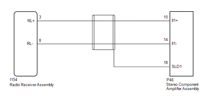
PROCEDURE
| 1. | CHECK HARNESS AND CONNECTOR (RADIO RECEIVER ASSEMBLY - STEREO COMPONENT AMPLIFIER ASSEMBLY) |
(a) Disconnect the I154 radio and display receiver assembly connector.
(b) Disconnect the P46 stereo component amplifier assembly connector.
(c) Measure the resistance according to the value(s) in the table below.
Standard Resistance:
| Tester connection | Condition | Specified condition |
|---|---|---|
| I154-3 (RL+) - P46-15 (II1+) | Always | Below 1 Ω |
| I154-8 (RL-) - P46-14 (II1-) | Always | Below 1 Ω |
| P46-18 (SLD1) - Body ground | Always | 10 kΩ or higher |
| I154-3 (RL+) or P46-15 (II1+) - Body ground | Always | 10 kΩ or higher |
| I154-8 (RL-) or P46-14 (II1-) - Body ground | Always | 10 kΩ or higher |
| OK | .gif) | PROCEED TO NEXT SUSPECTED AREA SHOWN IN PROBLEM SYMPTOMS TABLE |
.gif)
| NG | | REPAIR OR REPLACE HARNESS OR CONNECTOR |
READ NEXT:
 Microphone Circuit
DESCRIPTION
The radio receiver assembly and telephone microphone assembly are connected to each other using the microphone connection detection signal lines.
Using this circuit, the DCM (telemati
Visual Mute Signal Circuit between Radio Receiver and Multi-display
DESCRIPTION The radio receiver assembly sends a visual mute signal to the multi-display assembly. As a result, a black screen is inserted when the screen changes so that noise and distorted images are
Radio Receiver Power Source Circuit
DESCRIPTION This is the power source circuit to operate the radio receiver assembly. WIRING DIAGRAM CAUTION / NOTICE / HINT NOTICE:
Inspect the fuses for circuits related to this system before per
SEE MORE:
Initialization
INITIALIZATION NOTICE:
The necessary procedures (adjustment, calibration, initialization or registration) that must be performed after parts are removed and installed, or replaced during headlight ECU sub-assembly LH removal/installation are shown below. Performed Work or System Condition Ne
Removal
REMOVAL PROCEDURE 1. PRECAUTION Click here 2. REMOVE REAR BUMPER COVER Click here 3. REMOVE NO. 2 LUGGAGE ROOM WIRE Click here 4. REMOVE REAR CORNER ULTRASONIC SENSOR (a) Detach the 2 claws and remove the rear corner ultrasonic sensor. HINT:
When reusing the sensor, make sure that each s
