.gif)
- Power switch on (IG)
- Sound is input to the telephone microphone assembly when the user is closer than 125 mm (4.92 in.) from the telephone microphone assembly sound holes in the roof headlining holder cover.
Lexus NX: Microphone Circuit
Lexus NX Service Manual / Audio & Visual & Telematics / Audio / Video / Audio And Visual System / Microphone Circuit
DESCRIPTION
- The radio receiver assembly and telephone microphone assembly are connected to each other using the microphone connection detection signal lines.
-
Using this circuit, the DCM (telematics transceiver) sends power to the telephone microphone assembly, and the telephone microphone assembly sends microphone signals to the radio receiver assembly via the DCM (telematics transceiver)*.
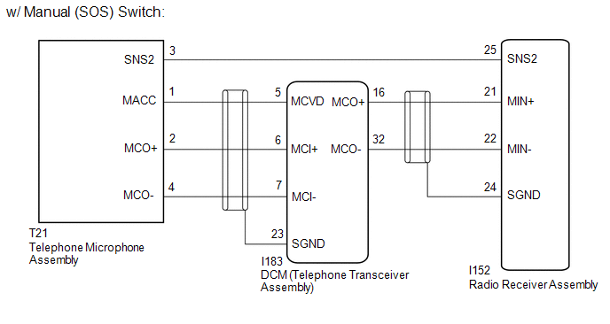
- *: w/ Manual (SOS) Switch
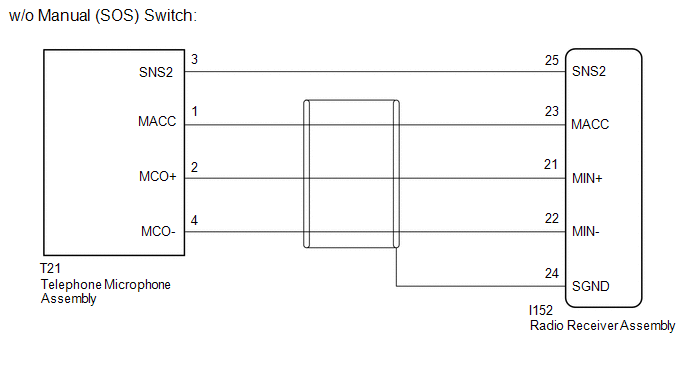
WIRING DIAGRAM
CAUTION / NOTICE / HINT
NOTICE:
-
When replacing the radio receiver assembly, always replace it with a new one.
If a radio receiver assembly which was installed to another vehicle is used, the following may occur:
- A communication malfunction DTC may be stored.
- The radio receiver assembly may not operate normally.
- When replacing the DCM (telematics transceiver), make sure to replace it with a new one (w/ Manual [SOS] Switch).
HINT:
Depending on the parts that are replaced during vehicle inspection or maintenance, performing initialization, registration or calibration may be needed. Refer to Precaution for Audio and Visual System (w/ Manual [SOS] Switch).
Click here .gif)
PROCEDURE
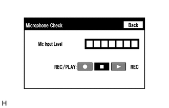
| 1. | CHECK MICROPHONE AND VOICE RECOGNITION |
| (a) Enter the "Microphone Check" screen. Refer to Check Microphone in Operation Check. Click here |
|
(b) When voice is input into the microphone, check that the microphone input level meter changes according to the input voice.
HINT:
The microphone is active at all times when "Microphone Check" screen is displayed.
(c) Push the recording switch and perform voice recording.
HINT:
- Select the recording switch with the blower motor of the air conditioning system stopped. If an outlet of the air conditioning system is facing the microphone, noise may be recorded.
- Voice can be recorded for up to 5 seconds.
(d) Check that the recording indicator remains on while recording and that the recorded voice is played normally without noise or distortion.
OK:
All check results are normal.
| OK | .gif) | PROCEED TO NEXT SUSPECTED AREA SHOWN IN PROBLEM SYMPTOMS TABLE |
|
| 2. | CHECK VEHICLE TYPE |
(a) Check the vehicle type.
| Result | Proceed to |
|---|---|
| w/ Manual (SOS) Switch | A |
| w/o Manual (SOS) Switch | B |
| B | | GO TO STEP 9 |
|
| 3. | CHECK HARNESS AND CONNECTOR (RADIO RECEIVER ASSEMBLY - TELEPHONE MICROPHONE ASSEMBLY) |
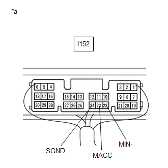
(a) Disconnect the I152 radio receiver assembly connector.
(b) Disconnect the T21 telephone microphone assembly connector.
(c) Measure the resistance according to the value(s) in the table below.
Standard Resistance:
| Tester Connection | Condition | Specified Condition |
|---|---|---|
| I152-25 (SNS2) - T21-3 (SNS2) | Always | Below 1 Ω |
| I152-25 (SNS2) - Body ground | Always | 10 kΩ or higher |
| NG | | REPAIR OR REPLACE HARNESS OR CONNECTOR |
|
| 4. | CHECK HARNESS AND CONNECTOR (RADIO RECEIVER ASSEMBLY - DCM [TELEMATICS TRANSCEIVER]) |
(a) Disconnect the I152 radio receiver assembly connector.
(b) Disconnect the I183 DCM (telematics transceiver) connector.
(c) Measure the resistance according to the value(s) in the table below.
Standard Resistance:
| Tester Connection | Condition | Specified Condition |
|---|---|---|
| I152-21 (MIN+) - I183-16 (MCO+) | Always | Below 1 Ω |
| I152-22 (MIN-) - I183-32 (MCO-) | Always | Below 1 Ω |
| I152-21 (MIN+) - Body ground | Always | 10 kΩ or higher |
| I152-22 (MIN-) - Body ground | Always | 10 kΩ or higher |
| I152-24 (SGND) - Body ground | Always | 10 kΩ or higher |
| NG | | REPAIR OR REPLACE HARNESS OR CONNECTOR |
|
| 5. | CHECK HARNESS AND CONNECTOR (DCM [TELEMATICS TRANSCEIVER] - TELEPHONE MICROPHONE ASSEMBLY) |
(a) Disconnect the I183 DCM (telematics transceiver) connector.
(b) Disconnect the T21 telephone microphone assembly connector.
(c) Measure the resistance according to the value(s) in the table below.
Standard Resistance:
| Tester Connection | Condition | Specified Condition |
|---|---|---|
| I183-5 (MCVD) - T21-1 (MACC) | Always | Below 1 Ω |
| I183-6 (MCI+) - T21-2 (MCO+) | Always | Below 1 Ω |
| I183-7 (MCI-) - T21-4 (MCO-) | Always | Below 1 Ω |
| I183-5 (MCVD) - Body ground | Always | 10 kΩ or higher |
| I183-6 (MCI+) - Body ground | Always | 10 kΩ or higher |
| I183-7 (MCI-) - Body ground | Always | 10 kΩ or higher |
| I183-23 (SGND) - Body ground | Always | 10 kΩ or higher |
| NG | | REPAIR OR REPLACE HARNESS OR CONNECTOR |
|
| 6. | CHECK DCM (TELEMATICS TRANSCEIVER) |
| (a) Remove the DCM (telematics transceiver) with the connector(s) still connected. Click here |
|
(b) Measure the voltage according to the value(s) in the table below.
Standard Voltage:
| Tester Connection | Switch Condition | Specified Condition |
|---|---|---|
| I183-5 (MCVD) - Body ground | Power switch on (IG) | 4 to 6 V |
(c) Measure the resistance according to the value(s) in the table below.
Standard Resistance:
| Tester Connection | Condition | Specified Condition |
|---|---|---|
| I183-23 (SGND) - Body ground | Always | Below 1 Ω |
| I183-7 (MCI-) - Body ground | Always | Below 1 Ω |
| NG | | REPLACE DCM (TELEMATICS TRANSCEIVER) |
|
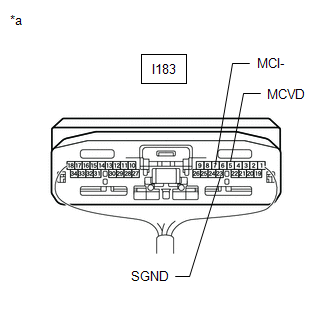
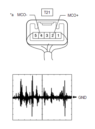
| 7. | CHECK TELEPHONE MICROPHONE ASSEMBLY (OUTPUT TO DCM [TELEMATICS TRANSCEIVER]) |

| *a | Component with harness connected (Telephone Microphone Assembly) |
(a) Check the output waveform.
(1) Remove the telephone microphone assembly with the connector(s) still connected.
Click here
(2) Connect an oscilloscope to terminal T21-2 (MCO+) and T21-4 (MCO-).
(3) Turn the power switch on (IG).
(4) Sound is input to the telephone microphone assembly when the user is closer than 125 mm (4.92 in.) from the telephone microphone assembly sound holes in the roof headlining holder cover.
(5) Check the signal waveform according to the condition(s) in the table below.
| Item | Condition |
|---|---|
| Measurement terminal | T21-2 (MCO+) - T21-4 (MCO-) |
| Tool setting | 50 mV/DIV., 500 ms/DIV. |
| Vehicle condition | |
OK:
The waveform is similar to that shown in the illustration.
HINT:
The oscilloscope waveform shown in the illustration is an example for reference only.
| NG | | REPLACE TELEPHONE MICROPHONE ASSEMBLY |
|
| 8. | CHECK DCM (TELEMATICS TRANSCEIVER) (OUTPUT TO RADIO RECEIVER ASSEMBLY) |
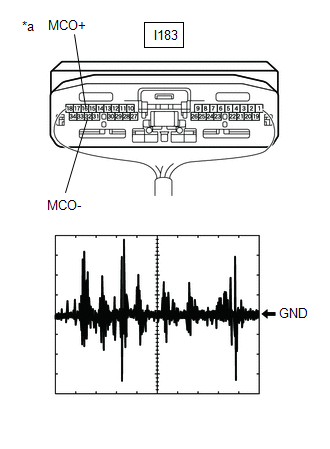
| *a | Component with harness connected (DCM [Telematics Transceiver]) |
(a) Check the output waveform.
(1) Remove the DCM (telematics transceiver) with the connector(s) still connected.
Click here
(2) Connect an oscilloscope to terminal I183-16 (MCO+) and I183-32 (MCO-).
(3) Turn the power switch on (IG).
(4) Sound is input to the telephone microphone assembly when the user is closer than 125 mm (4.92 in.) from the telephone microphone assembly sound holes in the roof headlining holder cover.
(5) Check the signal waveform according to the condition(s) in the table below.
| Item | Condition |
|---|---|
| Measurement terminal | I183-16 (MCO+) - I183-32 (MCO-) |
| Tool setting | 50 mV/DIV., 500 ms/DIV. |
| Vehicle condition |
|
OK:
The waveform is similar to that shown in the illustration.
HINT:
The oscilloscope waveform shown in the illustration is an example for reference only.
| OK | | REPLACE RADIO RECEIVER ASSEMBLY |
| NG | | REPLACE DCM (TELEMATICS TRANSCEIVER) |
| 9. | CHECK HARNESS AND CONNECTOR (RADIO RECEIVER ASSEMBLY - TELEPHONE MICROPHONE ASSEMBLY) |
(a) Disconnect the I152 radio receiver assembly connector.
(b) Disconnect the T21 telephone microphone assembly connector.
(c) Measure the resistance according to the value(s) in the table below.
Standard Resistance:
| Tester Connection | Condition | Specified Condition |
|---|---|---|
| I152-25 (SNS2) - T21-3 (SNS2) | Always | Below 1 Ω |
| I152-23 (MACC) - T21-1 (MACC) | Always | Below 1 Ω |
| I152-21 (MIN+) - T21-2 (MCO+) | Always | Below 1 Ω |
| I152-22 (MIN-) - T21-4 (MCO-) | Always | Below 1 Ω |
| I152-25 (SNS2) - Body ground | Always | 10 kΩ or higher |
| I152-23 (MACC) - Body ground | Always | 10 kΩ or higher |
| I152-21 (MIN+) - Body ground | Always | 10 kΩ or higher |
| I152-22 (MIN-) - Body ground | Always | 10 kΩ or higher |
| I152-24 (SGND) - Body ground | Always | 10 kΩ or higher |
| NG | | REPAIR OR REPLACE HARNESS OR CONNECTOR |
|
| 10. | CHECK RADIO RECEIVER ASSEMBLY |
| (a) Remove the radio receiver assembly with the connector(s) still connected. Click here |
|
(b) Measure the voltage according to the value(s) in the table below.
Standard Voltage:
| Tester Connection | Switch Condition | Specified Condition |
|---|---|---|
| I152-23 (MACC) - Body ground | Power switch on (IG) | 4 to 6 V |
(c) Measure the resistance according to the value(s) in the table below.
Standard Resistance:
| Tester Connection | Condition | Specified Condition |
|---|---|---|
| I152-22 (MIN-) - Body ground | Always | Below 1 Ω |
| I152-24 (SGND) - Body ground | Always | Below 1 Ω |
| NG | | REPLACE RADIO RECEIVER ASSEMBLY |
|
| 11. | CHECK TELEPHONE MICROPHONE ASSEMBLY (OUTPUT TO RADIO RECEIVER ASSEMBLY) |
| *a | Component with harness connected (Telephone Microphone Assembly) |
(a) Check the output waveform.
(1) Remove the telephone microphone assembly with the connector(s) still connected.
Click here
(2) Connect an oscilloscope to terminal T21-2 (MCO+) and T21-4 (MCO-).
(3) Turn the power switch on (IG).
(4) Sound is input to the telephone microphone assembly when the user is closer than 125 mm (4.92 in.) from the telephone microphone assembly sound holes in the roof headlining holder cover.
(5) Check the signal waveform according to the condition(s) in the table below.
| Item | Condition |
|---|---|
| Measurement terminal | T21-2 (MCO+) - T21-4 (MCO-) |
| Tool setting | 50 mV/DIV., 500 ms/DIV. |
| Vehicle condition |
|
OK:
The waveform is similar to that shown in the illustration.
HINT:
The oscilloscope waveform shown in the illustration is an example for reference only.
| OK | | REPLACE RADIO RECEIVER ASSEMBLY |
| NG | | REPLACE TELEPHONE MICROPHONE ASSEMBLY |
READ NEXT:
 Visual Mute Signal Circuit between Radio Receiver and Multi-display
DESCRIPTION The radio receiver assembly sends a visual mute signal to the multi-display assembly. As a result, a black screen is inserted when the screen changes so that noise and distorted images are
Radio Receiver Power Source Circuit
DESCRIPTION This is the power source circuit to operate the radio receiver assembly. WIRING DIAGRAM CAUTION / NOTICE / HINT NOTICE:
Inspect the fuses for circuits related to this system before per
SEE MORE:
On-vehicle Inspection
ON-VEHICLE INSPECTION CAUTION / NOTICE / HINT CAUTION: Be sure to correctly follow the removal and installation procedures for the front seat outer belt assembly. PROCEDURE 1. INSPECT FRONT SEAT OUTER BELT ASSEMBLY (for Vehicle not Involved in Collision) (a) Perform a diagnostic system check. Click
Throttle Actuator Control Motor Circuit Low (P2102,P2103)
DESCRIPTION The throttle actuator is operated by the ECM and opens and closes the throttle valve using gears. The opening angle of the throttle valve is detected by the throttle position sensor, which is mounted on the throttle body with motor assembly. The throttle position sensor provides feedback
© 2016-2026 Copyright www.lexunx.com
