Lexus NX: Brake Control Warning Light Remains ON
DESCRIPTION
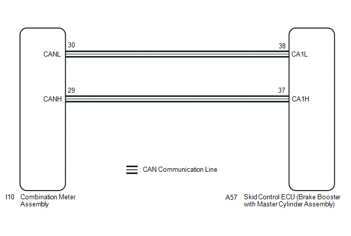
The skid control ECU (brake booster with master cylinder assembly) is connected to the combination meter assembly via CAN communication.
If the skid control ECU stores a DTC, the brake warning light / yellow (minor malfunction) comes on in the combination meter assembly.
WIRING DIAGRAM
CAUTION / NOTICE / HINT
NOTICE:
When replacing the skid control ECU (brake booster with master cylinder assembly), perform initialization and calibration of the linear solenoid valve.
Click here .gif)
PROCEDURE
| 1. | CHECK CAN COMMUNICATION SYSTEM |
(a) Check if CAN communication system DTCs are output.
Click here
| Result | Proceed to |
|---|---|
| DTCs are not output. | A |
| DTCs are output. | B |
| B | .gif) | INSPECT CAN COMMUNICATION SYSTEM |
|
.gif)
| 2. | CHECK IF BRAKE BOOSTER WITH MASTER CYLINDER ASSEMBLY CONNECTOR IS SECURELY CONNECTED |
(a) Check if the skid control ECU (brake booster with master cylinder assembly) connector is securely connected.
OK:
The connector is securely connected.
| NG | | CONNECT CONNECTOR TO BRAKE BOOSTER WITH MASTER CYLINDER ASSEMBLY CORRECTLY |
|
| 3. | CHECK AUXILIARY BATTERY |
(a) Check the auxiliary battery voltage.
Standard Voltage:
| Tester Connection | Switch Condition | Specified Condition |
|---|---|---|
| Auxiliary battery | Power switch on (IG) | 11 to 14 V |
| Auxiliary battery | Power switch on (READY) | 11 to 15.5 V |
| NG | | CHARGE OR REPLACE AUXILIARY BATTERY |
|
| 4. | READ VALUE USING TECHSTREAM (BRAKE WARNING LIGHT / YELLOW (MINOR MALFUNCTION)) |
(a) Connect the Techstream to the DLC3.
(b) Turn the power switch on (IG).
(c) Select the Data List on the Techstream.
Click here
| Tester Display | Measurement Item | Range | Normal Condition | Diagnostic Note |
|---|---|---|---|---|
| ECB Warning Light | Brake warning light / yellow (minor malfunction) | ON or OFF | ON: Warning light on OFF: Warning light off | ECB: Electronically Controlled Brake System |
| Tester Display |
|---|
| ECB Warning Light |
(d) Check the Techstream display condition of the brake warning light / yellow (minor malfunction).
| Result | Proceed to |
|---|---|
| Display of the Data List remains OFF. | A |
| Display of the Data List remains ON. | B |
| A | | INSPECT METER / GAUGE SYSTEM |
| B | | REPLACE BRAKE BOOSTER WITH MASTER CYLINDER ASSEMBLY |
READ NEXT:
 Brake Control Warning Light does not Come ON
DESCRIPTION The skid control ECU (brake booster with master cylinder assembly) is connected to the combination meter assembly via CAN communication. CAUTION / NOTICE / HINT NOTICE: When replacing the
Brake Hold Standby Indicator Light Circuit
DESCRIPTION The brake hold standby indicator light turns on if brake hold control is possible when the following conditions required for operation standby are met and the brake hold switch (integratio
Slip Indicator Light Remains ON
DESCRIPTION The skid control ECU (brake booster with master cylinder assembly) is connected to the combination meter assembly via CAN communication. If the skid control ECU (brake booster with master
SEE MORE:
Radio Broadcast cannot be Received or Poor Reception
WIRING DIAGRAM CAUTION / NOTICE / HINT NOTICE: When replacing the radio receiver assembly, always replace it with a new one. If a radio receiver assembly which was installed to another vehicle is used, the following may occur:
A communication malfunction DTC may be stored.
The radio receiver a
Components
COMPONENTS ILLUSTRATION *1 FRONT DOOR INSIDE HANDLE BEZEL PLUG LH *2 FRONT DOOR TRIM BOARD SUB-ASSEMBLY LH *3 FRONT DOOR TRIM COVER LH *4 FRONT SEAT SLIDE SWITCH BEZEL *5 POWER WINDOW REGULATOR MASTER SWITCH ASSEMBLY WITH FRONT DOOR ARMREST BASE PANEL *6 SEAT MEMORY SWI
