Lexus NX: Brake Hold Standby Indicator Light Circuit
DESCRIPTION
The brake hold standby indicator light turns on if brake hold control is possible when the following conditions required for operation standby are met and the brake hold switch (integration control and panel assembly) is turned on while the power switch is on (IG).
-
Conditions required for operation standby:
- The driver's door is closed.
- Driver's seat belt is fastened.
- The system is normal.
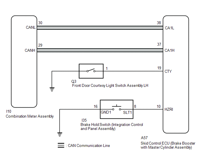
WIRING DIAGRAM
CAUTION / NOTICE / HINT
HINT:
When replacing the skid control ECU (brake booster with master cylinder assembly), perform initialization and calibration of the linear solenoid valve.
Click here .gif)
PROCEDURE
| 1. | PRE-CHECK |
(a) If the brake hold standby indicator light does not illuminate even though the brake hold switch (integration control and panel assembly) is pushed, check that the brake hold function operation conditions are met.
- The driver's door is closed.
- Driver's seat belt is fastened.
- The system is normal.
HINT:
If a malfunction occurs in one of the following systems, the brake hold operated indicator light will blink. If this occurs, perform troubleshooting on the malfunctioning system.
- Brake system
- Electric parking brake system
- Hybrid control system
|
.gif)
| 2. | CHECK CAN COMMUNICATION SYSTEM |
(a) Check if CAN communication system DTCs are output.
Click here
| Result | Proceed to |
|---|---|
| DTCs are not output. | A |
| DTCs are output. | B |
| B | .gif) | INSPECT CAN COMMUNICATION SYSTEM |
|
| 3. | PERFORM ACTIVE TEST USING TECHSTREAM (BRAKE HOLD STANDBY INDICATOR LIGHT) |
(a) Connect the Techstream to the DLC3.
(b) Turn the power switch on (IG).
(c) Select the Active Test on the Techstream.
Click here
| Tester Display | Measurement Item | Control Range | Diagnostic Note |
|---|---|---|---|
| BH Standby Light | Brake hold standby indicator light | Indicator light ON/OFF | Observe combination meter |
(d) Select the Data List on the Techstream.
Click here
| Tester Display | Measurement Item | Range | Normal Condition | Diagnostic Note |
|---|---|---|---|---|
| BH Standby Light | Brake hold standby indicator light | ON or OFF | ON: Indicator light on OFF: Indicator light off | - |
| Active Test Display |
|---|
| BH Standby Light |
| Data List Display |
|---|
| BH Standby Light |
(e) Check the operating condition of the brake hold standby indicator light when operating it using the Techstream.
| Result | Proceed to |
|---|---|
| Brake hold standby indicator light in the Data List does not change using the Active Test. | A |
| Brake hold standby indicator light in the Data List turns ON/OFF using the Active Test. | B |
| A | | REPLACE BRAKE BOOSTER WITH MASTER CYLINDER ASSEMBLY |
|
| 4. | INSPECT COMBINATION METER ASSEMBLY |
(a) Turn the power switch off.
(b) Perform the Active Test of the combination meter assembly (meter CPU) using the Techstream.
Click here
| Tester Display |
|---|
| Indicat. Brake Hold |
(c) Check the combination meter assembly.
OK:
The brake hold standby indicator light turns on or off in accordance with the Techstream operation.
| NG | | INSPECT METER / GAUGE SYSTEM |
|
| 5. | INSPECT INTEGRATION CONTROL AND PANEL ASSEMBLY |
(a) Turn the power switch off.
(b) Remove the brake hold switch (integration control and panel assembly).
Click here
(c) Inspect the brake hold switch (integration control and panel assembly).
Click here
OK:
The brake hold switch (integration control and panel assembly) operates normally.
| NG | | REPLACE INTEGRATION CONTROL AND PANEL ASSEMBLY |
|
| 6. | CHECK HARNESS AND CONNECTOR (BRAKE BOOSTER WITH MASTER CYLINDER ASSEMBLY - INTEGRATION CONTROL AND PANEL ASSEMBLY) |
(a) Disconnect the A57 skid control ECU (brake booster with master cylinder assembly) connector.
(b) Measure the resistance according to the value(s) in the table below.
Standard Resistance:
| Tester Connection | Condition | Specified Condition |
|---|---|---|
| A57-10 (HZRI) - I35-8 (SLT1) | Always | Below 1 Ω |
| A57-10 (HZRI) or I35-8 (SLT1) - Body ground | Always | 10 kΩ or higher |
| I35-16 (GND1) - Body ground | Always | Below 1 Ω |
| NG | | REPAIR OR REPLACE HARNESS OR CONNECTOR |
|
| 7. | INSPECT FRONT DOOR COURTESY LIGHT SWITCH ASSEMBLY |
(a) Turn on the interior lights and check that they illuminate, and then set the switch so that the lights illuminate when the door is opened.
(b) Check that the lights illuminate when the driver door is opened.
OK:
The interior lights illuminate when the driver door is opened.
| NG | | INSPECT LIGHTING SYSTEM |
|
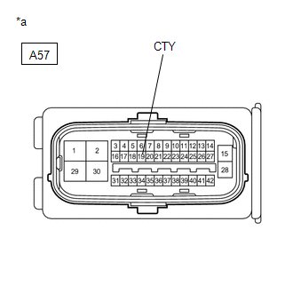
| 8. | CHECK HARNESS AND CONNECTOR (CTY TERMINAL) |
| (a) Measure the voltage according to the value(s) in the table below. Standard Voltage:
|
|
| OK | | REPLACE BRAKE BOOSTER WITH MASTER CYLINDER ASSEMBLY |
| NG | | REPAIR OR REPLACE HARNESS OR CONNECTOR (CTY CIRCUIT) |
READ NEXT:
 Slip Indicator Light Remains ON
DESCRIPTION The skid control ECU (brake booster with master cylinder assembly) is connected to the combination meter assembly via CAN communication. If the skid control ECU (brake booster with master
Slip Indicator Light does not Come ON
DESCRIPTION The skid control ECU (brake booster with master cylinder assembly) is connected to the combination meter assembly via CAN communication. CAUTION / NOTICE / HINT NOTICE: When replacing the
VSC OFF Switch Circuit
DESCRIPTION The skid control ECU assembly is connected to the combination meter assembly via CAN communication. Pressing the VSC OFF switch turns off TRAC operation, and pressing and holding this swit
SEE MORE:
How To Proceed With Troubleshooting
CAUTION / NOTICE / HINT HINT:
Use the following procedure to troubleshoot the sliding roof system.
*: Use the Techstream.
PROCEDURE 1. VEHICLE BROUGHT TO WORKSHOP
NEXT 2. CUSTOMER PROBLEM ANALYSIS HINT:
In troubleshooting, confirm that the problem sympto
Operation Check
OPERATION CHECK INSPECT ASC SYSTEM OPERATION CAUTION: Check for safety before performing any tests. HINT: When the drive mode changes to a mode other than NORMAL, SPORT or CUSTOMIZE*, the simulated engine sound stops. *: Customize mode refers to when the following conditions are set on the multi-dis
