Lexus NX: Buzzer Circuit Short to Ground or Open (C1A4A14)
DESCRIPTION
If the forward recognition camera detects an open or short to ground in the buzzer circuit, it will store DTC C1A4A14.
| DTC No. | Detection Item | DTC Detection Condition | Trouble Area |
|---|---|---|---|
| C1A4A14 | Buzzer Circuit Short to Ground or Open | The forward recognition camera detects an open or short to ground in the buzzer circuit for 2 seconds or more. |
|
WIRING DIAGRAM
.png)
CAUTION / NOTICE / HINT
NOTICE:
- Inspect the fuses for circuits related to this system before performing the following procedure.
- When replacing the forward recognition camera, always replace it with a new one. If a forward recognition camera which was installed to another vehicle is used, the information stored in the forward recognition camera will not match the information from the vehicle. As a result, a DTC may be stored.
-
If the forward recognition camera has been replaced with a new one, be sure to perform forward recognition camera adjustment.
HINT:
Forward recognition camera adjustment can be performed by using either One Time Recognition or Sequential Recognition.
One Time Recognition: Click here
.gif)
Sequential Recognition: Click here
PROCEDURE
| 1. | CHECK FOR DTCs |
(a) Clear the DTCs.
Chassis > Front Recognition Camera > Clear DTCs(b) Make sure that the DTC detection conditions are met.
HINT:
If the detection conditions are not met, the system cannot detect the malfunction.
(c) Check for DTCs.
Chassis > Front Recognition Camera > Trouble Codes| Result | Proceed to |
|---|---|
| DTC C1A4A14 is not output | A |
| DTC C1A4A14 is output | B |
| A | .gif) | USE SIMULATION METHOD TO CHECK |
|
.gif)
| 2. | CHECK HARNESS AND CONNECTOR (SKID CONTROL BUZZER BATTERY CIRCUIT) |
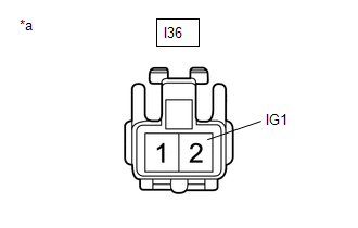
| *a | Front view of wire harness connector (to skid control buzzer) |
(a) Disconnect the I36 skid control buzzer connector.
(b) Measure the voltage according to the value(s) in the table below.
Standard Voltage:
| Tester Connection | Switch Condition | Specified Condition |
|---|---|---|
| I36-2 (IG1) - Body ground | Power switch on (IG) | 8 to 16 V |
| Power switch off | Below 1 V |
(c) Connect the I36 skid control buzzer connector.
| NG | | REPAIR OR REPLACE HARNESS OR CONNECTOR (SKID CONTROL BUZZER BATTERY CIRCUIT) |
|
| 3. | CHECK HARNESS AND CONNECTOR (SKID CONTROL BUZZER - FORWARD RECOGNITION CAMERA) |
(a) Disconnect the I36 skid control buzzer connector.
(b) Disconnect the T18 forward recognition camera connector.
(c) Measure the resistance according to the value(s) in the table below.
Standard Resistance:
| Tester Connection | Condition | Specified Condition |
|---|---|---|
| I36-1 (BZ) - T18-8 (BZ) | Always | Below 1 Ω |
| I36-1 (BZ) or T18-8 (BZ) - Body ground | Always | 10 kΩ higher |
(d) Connect the T18 forward recognition camera connector.
(e) Connect the I36 skid control buzzer connector.
| NG | | REPAIR OR REPLACE HARNESS OR CONNECTOR (SKID CONTROL BUZZER - FORWARD RECOGNITION CAMERA) |
|
| 4. | INSPECT SKID CONTROL BUZZER |
(a) Remove the skid control buzzer.
Click here
(b) Inspect the skid control buzzer.
Click here
| OK | | REPLACE FORWARD RECOGNITION CAMERA |
| NG | | REPLACE SKID CONTROL BUZZER |
READ NEXT:
 Steering Vibrator System Missing Message (C1A7587)
DESCRIPTION The forward recognition camera communicates with the steering vibration ECU via LIN communication. If a communication error between the forward recognition camera and steering vibration EC
Front Recognition Camera Optical Axis Misalignment Malfunction (C1AA800)
DESCRIPTION If the forward recognition camera determines that the beam axis of the camera is misaligned, it stores C1AA800. DTC No. Detection Item DTC Detection Condition Trouble Area C1A
Front Recognition Camera Heater Malfunction (C1AAE00)
DESCRIPTION The forward recognition camera controls the current to the forward recognition hood with heater sub-assembly. C1AAE00 is stored when the forward recognition camera detects a forward recogn
SEE MORE:
Installation
INSTALLATION PROCEDURE 1. INSTALL ELECTRICAL KEY ANTENNA NOTICE: Do not reuse dropped or damaged parts. (a) Attach the guide and install the electrical key antenna with the nut. Torque: 7.5 N·m {76 kgf·cm, 66 in·lbf} (b) Connect the connector. 2. INSTALL REAR BUMPER COVER Click here 3. INSTA
Rough Idling (P1605)
DESCRIPTION When the engine is idling stably under a low load, if the idle speed drops or becomes unstable, this DTC will be stored. Read freeze frame data using the Techstream. The ECM records vehicle and driving condition information as freeze frame data the moment a DTC is stored. When troublesho
