Lexus NX: Front Recognition Camera Heater Malfunction (C1AAE00)
DESCRIPTION
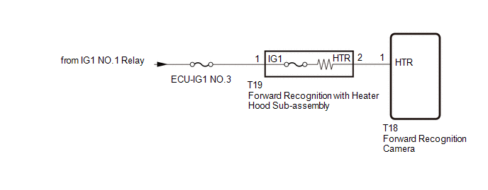
The forward recognition camera controls the current to the forward recognition hood with heater sub-assembly.
C1AAE00 is stored when the forward recognition camera detects a forward recognition hood with heater sub-assembly operation circuit malfunction.
| DTC No. | Detection Item | DTC Detection Condition | Trouble Area |
|---|---|---|---|
| C1AAE00 | Front Recognition Camera Heater Malfunction | When 10 seconds elapse after turning the power switch on (IG), the forward recognition camera determines that one of the following conditions is met
|
|
| Vehicle Condition | ||||
| Pattern 1 | Pattern 2 | Pattern 3 | ||
| Detection condition | 10 seconds elapse after turning the power switch on (IG) | ○ | ○ | ○ |
| Malfunction status | Supply fault in hot wire circuit | ○ | - | - |
| Open circuit in hot wire circuit | - | ○ | - | |
| Short to GND in hot wire circuit | - | - | ○ | |
| Malfunction duration | 1 second or more continuously | 5 seconds or more continuously | 5 seconds or more continuously | |
| Number of trips | 1 trip | 1 trip | 1 trip | |
HINT:
The DTC is output when a combination of any of the above conditions are met.
WIRING DIAGRAM
CAUTION / NOTICE / HINT
NOTICE:
- Inspect the fuses for circuits related to this system before performing the following procedure.
- When replacing the forward recognition camera, always replace it with a new one. If a forward recognition camera which was installed to another vehicle is used, the information stored in it will not match the information from the vehicle and a DTC may be stored.
-
If the forward recognition camera has been replaced with a new one, be sure to perform forward recognition camera adjustment.
HINT:
Forward recognition camera adjustment can be performed by using either "One Time Recognition" or "Sequential Recognition".
One Time Recognition:
Click here
.gif)
Sequential Recognition:
Click here
PROCEDURE
| 1. | CHECK FOR DTC |
(a) Clear the DTCs.
Click here
(b) Make sure that the DTC detection conditions are met.
HINT:
If the conditions are not met, the system cannot detect the malfunction.
Click here
(c) Recheck for DTCs and check that no DTCs are output.
Click here
OK:
DTC C1AAE00 is not output.
| OK | .gif) | USE SIMULATION METHOD TO CHECK |
|
.gif)
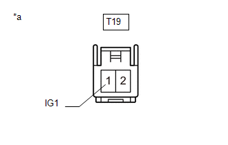
| 2. | CHECK FORWARD RECOGNITION WITH HEATER HOOD SUB-ASSEMBLY |
| (a) Turn the power switch off. |
|
(b) Disconnect the T19 forward recognition with heater hood sub-assembly connector.
(c) Measure the resistance according to the value(s) in the table below.
Standard Resistance:
| Tester Connection | Switch Condition | Specified Condition |
|---|---|---|
| 1 (IG1) - 2 (HTR) | Power switch off | 28.5 to 31.5 Ω |
| NG | | REPLACE FORWARD RECOGNITION WITH HEATER HOOD SUB-ASSEMBLY |
|
| 3. | CHECK HARNESS AND CONNECTOR (FORWARD RECOGNITION WITH HEATER HOOD SUB-ASSEMBLY - BATTERY) |
| (a) Disconnect the forward recognition with heater hood sub-assembly connector. |
|
(b) Measure the voltage according to the value(s) in the table below.
Standard Voltage:
| Tester Connection | Switch Condition | Specified Condition |
|---|---|---|
| T19-1 (IG1) - Body ground | Power switch on (IG) | 8 to 16 V |
| Power switch off | Below 1.5 V |
| NG | | REPAIR OR REPLACE HARNESS OR CONNECTOR |
|
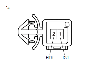
| 4. | CHECK HARNESS AND CONNECTOR (FORWARD RECOGNITION WITH HEATER HOOD SUB-ASSEMBLY - FORWARD RECOGNITION CAMERA) |
(a) Disconnect the T19 forward recognition with heater hood sub-assembly connector.
(b) Disconnect the T18 forward recognition camera connector.
(c) Measure the resistance according to the value(s) in the table below.
Standard Resistance:
| Tester Connection | Condition | Specified Condition |
|---|---|---|
| T19-2 (HTR) - T18-1 (HTR) | Always | Below 1 Ω |
| T19-2 (HTR) or T18-1 (HTR) - Body ground | Always | 10 kΩ or higher |
(d) Reconnect the T18 forward recognition camera connector.
(e) Reconnect the T19 forward recognition with heater hood sub-assembly connector.
| OK | | REPLACE FORWARD RECOGNITION CAMERA |
| NG | | REPAIR OR REPLACE HARNESS OR CONNECTOR |
READ NEXT:
 Lost Communication with Multi-axis Acceleration Sensor Module Missing Message (U012587,U012687,U012987,U014087,U029387)
DESCRIPTION DTC No. Detection Item DTC Detection Condition Trouble Area U012587 Lost Communication with Multi-axis Acceleration Sensor Module Missing Message 3 seconds after the power
Internal Control Module Software Incompatibility Not Programmed (U030051,U030057)
DESCRIPTION
The forward recognition camera receives vehicle information (Conv/HV) from the hybrid vehicle control ECU via the CAN communication line.
When the forward recognition camera is unable
Software Incompatibility with Body Control Module Not Programmed (U032251)
DESCRIPTION The forward recognition camera receives vehicle specification information from the main body ECU (multiplex network body ECU) via the CAN communication line. When the forward recognition c
SEE MORE:
Removal
REMOVAL PROCEDURE 1. REMOVE DECK BOARD ASSEMBLY Click here 2. REMOVE NO. 3 DECK BOARD SUB-ASSEMBLY Click here 3. REMOVE REAR DECK FLOOR BOX Click here 4. REMOVE DECK FLOOR BOX LH Click here 5. PRECAUTION CAUTION: Be sure to read Precaution thoroughly before serving. Click here NOTICE: Afte
Problem Symptoms Table
PROBLEM SYMPTOMS TABLE HINT: Use the table below to help determine the cause of problem symptoms. If multiple suspected areas are listed, the potential causes of the symptoms are listed in order of probability in the "Suspected Area" column of the table. Check each symptom by checking the suspected
