- Removal and installation of the steering sensor
- Removal and installation of the connector of the steering sensor
- Replacement
Lexus NX: Calibration
CALIBRATION
NOTICE:
When any of the following parts have been replaced, perform adjustment shown in the following table. If not, the intelligent clearance sonar system may not operate correctly.
PRECAUTION
(a) The necessary procedures (adjustment, calibration, initialization or registration) that must be performed after parts are removed and installed, or replaced during intelligent clearance sonar system removal/installation are shown below.
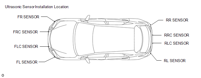
For the installation location of the ultrasonic sensors, refer to Parts Location.
Click here .gif)
| Part Name | Operation | Adjustment Item | Proceed to |
|---|---|---|---|
| Steering sensor | | Steering angle neutral point (Initialize intelligent clearance sonar system) | Procedure 3 |
| Suspension, tires, etc. | The vehicle height changes because of suspension or tire replacement | Measurement of ultrasonic sensor detection angle | Procedure 1, 2 |
| Ultrasonic sensor detection angle registration | Procedure 3 | ||
| Front bumper assembly |
| Measurement of ultrasonic sensor detection angle | Procedure 1, 2 |
| Ultrasonic sensor detection angle registration | Procedure 3 | ||
| Rear bumper assembly |
| Measurement of ultrasonic sensor detection angle | Procedure 1, 2 |
| Ultrasonic sensor detection angle registration | Procedure 3 | ||
| Clearance warning ECU assembly | Replacement | Measurement of ultrasonic sensor detection angle | Procedure 1, 2 |
| Steering angle neutral point | Procedure 3 | ||
| Bumper type registration | |||
| Ultrasonic sensor detection angle registration | |||
| Ultrasonic sensor |
| Measurement of ultrasonic sensor detection angle | Procedure 1, 2 |
| Ultrasonic sensor detection angle registration | Procedure 3 | ||
| An ultrasonic sensor becomes misaligned | Measurement of ultrasonic sensor detection angle | Procedure 1, 2 | |
| Ultrasonic sensor detection angle registration | Procedure 3 | ||
| An ultrasonic sensor is subjected to impact | Measurement of ultrasonic sensor detection angle | Procedure 1, 2 | |
| Ultrasonic sensor detection angle registration | Procedure 3 | ||
| Auxiliary battery | Cable is disconnected from the negative (-) auxiliary battery terminal | Steering angle neutral point* | Procedure 3 |
*: The steering sensor zero point can also be calibrated by driving the vehicle.
Click here
PREPARATION (PROCEDURE 1)
(a) Preparation
- Digital angle gauge
- Digital angle gauge attachment
- Masking tape (To prevent damage)
- A level
SST: 09989-00020
(b) Confirm levelness of floor surface.
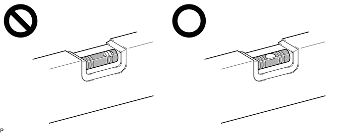
(1) Place a bubble level on a level surface and confirm that the bubble is centered.
NOTICE:
Make sure that there is no gravel, sand, etc., and that the surface is not undulating.
HINT:
By adjusting the direction of the bubble level, it is possible to find a position where the bubble is centered.
(2) Turn on the digital angle gauge.
(3) Place the digital angle gauge in the same location and direction as that of the bubble level where the levelness of the surface was confirmed.
NOTICE:
Confirm that the location and direction of the digital angle gauge is exactly the same as that of the bubble level.
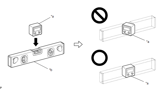
| *a | Digital Angle Gauge | *b | Level |
(4) Press the "ZERO" switch to memorize the zero point (perfectly level).
NOTICE:
Make sure that the digital angle gauge does not move when pressing the switch. If the digital angle gauge moves when the switch is pressed, an incorrect zero point may be memorized and it will not be possible to accurately check for levelness.
(5) Using the digital angle gauge in which the zero point (perfectly level) has been memorized, measure the angle of the floor surface at the 4 positions at the front of the vehicle and the 4 positions at the rear of the vehicle as shown in the illustration.
NOTICE:
- Always position the digital angle gauge as shown in the illustration.
- Make sure that there is no gravel, sand, etc., and that the floor surface is not undulating.
- When measuring the angle of the floor surface, avoid uneven areas such as joints between tiles.
HINT:
If necessary, the digital angle gauge can be placed anywhere within the specified area when measuring the angle of the floor surface for positions A, C, F and H.
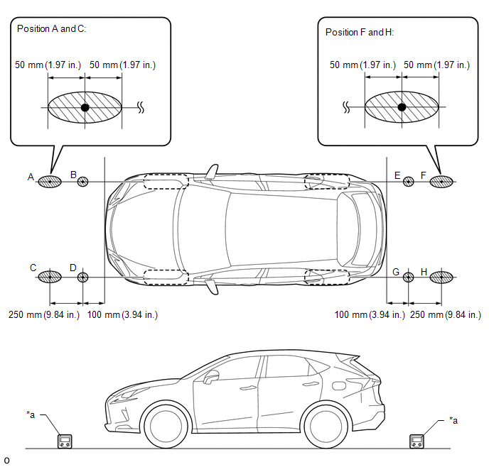
.png) | Confirmation Area | - | - |
| *a | Digital angle gauge | - | - |
(6) Using the following worksheet, calculate the average of the measurements taken at the 4 positions in front of the vehicle, and calculate the average of the measurements taken at the 4 positions behind the vehicle. Confirm that the front measurement average and the rear measurement average are not more than approximately 0.37 degrees. Also, confirm that the front measurement average and the rear measurement average is less than 0.2 degrees.
NOTICE:
If the front measurement average and the rear measurement average are more than approximately 0.37 degrees or the difference between the front measurement average and the rear measurement average is 0.2 degrees or more, choose another work area as it is not possible to accurately check the installation angle of the sensors.
Worksheet: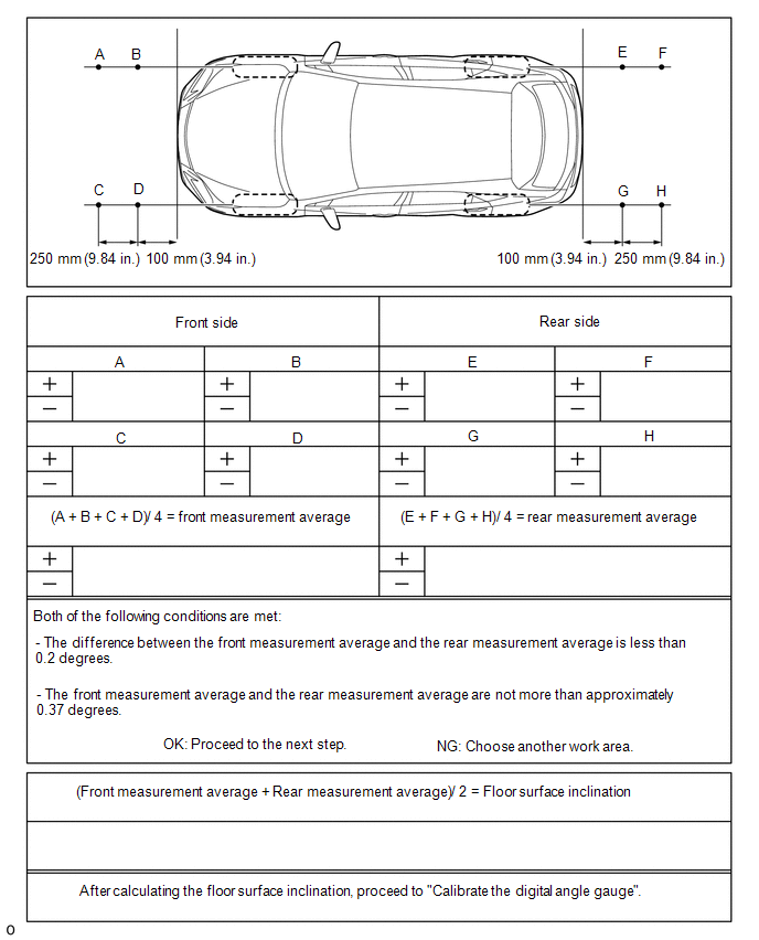
(7) Average the front measurement average and the rear measurement average, then round the answer to 1 decimal place (E.g. 0.0927 degrees is rounded to 0.1 degrees) to obtain the floor surface inclination value.
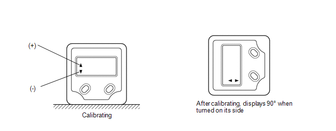
(8) Calibrate the digital angle gauge
Adjust the angle of the digital angle gauge until it reads the same value of the floor surface inclination, then press the "ZERO" switch to memorize the zero point (level with floor surface).
NOTICE:
Before pressing the "ZERO" switch, confirm that the digital angle gauge reading is positive if the floor angle inclination is positive, and negative if the floor angle inclination is negative.
(c) Prepare the digital angle gauge
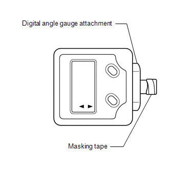
(1) Attach the digital angle gauge attachment to the digital angle gauge.
SST: 09989-00020
(2) Attach masking tape to the digital angle gauge attachment.
(d) Remove all luggage from the vehicle.
(e) Adjust the tire inflation pressure to the specified pressure.
Click here
(f) Check the height of the vehicle.
Click here
SENSOR HEIGHT AND ALIGNMENT INSPECTION (PROCEDURE 2)
HINT:
Check if the installation angle of each ultrasonic sensor is appropriate.
(a) Preparation
(1) Visually check that the bumper, grille and ultrasonic sensors are installed properly and are not damaged.
NOTICE:
If the bumper, grille or any ultrasonic sensor is not installed correctly, the calibration may not be able to be completed.
(2) Check the tire pressures and adjust them if necessary.
Click here
NOTICE:
- Ensure that the vehicle is level in an area with no wind.
- Do not lean on the vehicle.
- Do not do anything that may affect the level of the vehicle during the calibration, such as getting in or out of the vehicle, or adding or removing luggage.
(b) Sensor height and alignment inspection
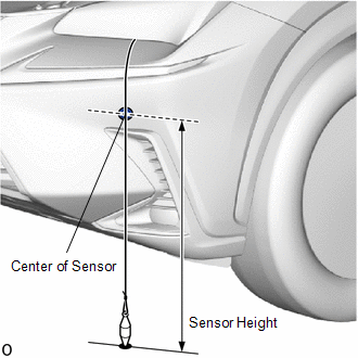
(c) Measure the installation height of the sensors.
except Sport Package:
Standard Height (Front Bumper):| Sensor Location | Sensor Height |
|---|---|
| Front Center Ultrasonic Sensor | 520.6 to 573.7 mm (20.5 to 22.6 in.) |
| Front Corner Ultrasonic Sensor | 627.3 to 680.4 mm (24.7 to 26.8 in.) |
for Sport Package:
Standard Height (Front Bumper):| Sensor Location | Sensor Height |
|---|---|
| Front Center Ultrasonic Sensor | 537.5 to 590.6 mm (21.2 to 23.3 in.) |
| Front Corner Ultrasonic Sensor | 538.2 to 591.3 mm (21.2 to 23.3 in.) |
Standard Height (Rear Bumper):
| Sensor Location | Sensor Height |
|---|---|
| Rear Center Ultrasonic Sensor | 511.6 to 695.1 mm (20.1 to 27.4 in.) |
| Rear Corner Ultrasonic Sensor | 513.5 to 693.1 mm (20.2 to 27.3 in.) |
NOTICE:
If the installation height of a sensor is not as specified, it may not be possible to measure the sensor angles correctly. If so, unload the vehicle and measure the installation height of the sensors again.
HINT:
Use the center of the sensor as the measuring point.
(d) Using the digital angle gauge, measure the angle of each sensor.
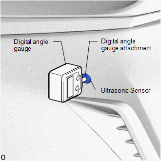
(1) Measure the angle of the front sensors as shown in the illustration.
NOTICE:
Ensure that the digital angle gauge is flush with the face of the sensor.
(2) Measure the angle of the rear sensors.
NOTICE:
Ensure that the digital angle gauge is flush with the face of the sensor.
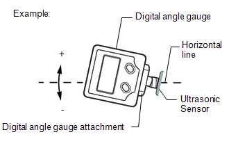
(3) Confirm that the angles of the sensors are as specified.
NOTICE:
The sensor angle is the measured sensor angle subtracted from 90°.
HINT:
- The digital angle gauge should indicate 90° when turned on its side.
- If the face of the sensor is tilted upwards, the sensor angle will be positive.
except Sport Package:
Standard Angle (Front Bumper):| Sensor Location | Installation Angle |
|---|---|
| Front Center Ultrasonic Sensor | -1.81 to 4.36° |
| Front Corner Ultrasonic Sensor | -5.11 to 1.06° |
for Sport Package:
Standard Angle (Front Bumper):| Sensor Location | Installation Angle |
|---|---|
| Front Center Ultrasonic Sensor | -1.81 to 4.36° |
| Front Corner Ultrasonic Sensor | -1.81 to 4.36° |
Standard Angle (Rear Bumper):
| Sensor Location | Installation Angle |
|---|---|
| Rear Center Ultrasonic Sensor | 1.44 to 7.61° |
| Rear Corner Ultrasonic Sensor | 1.34 to 7.51° |
(4) If the angle or height of the sensors is not as specified, confirm that the installation is correct and then perform the inspection again.
REGISTRATION (PROCEDURE 3)
(a) Preparation
(1) Confirm that the following DTCs are not output.
| System | Proceed to |
|---|---|
| Intuitive Parking Assist System (w/ Intelligent Clearance Sonar System) | |
| Intelligent Clearance Sonar System | |
NOTICE:
If DTC C1AEC, C1AED, C1AF0, C1AF3, C1AF4, C1AEA or C168D are output at this point, it is not a malfunction. Proceed with the calibration.
(b) Connect the Techstream to the DLC3.
(c) Turn the power switch on (IG).
(d) Turn the Techstream on.
(e) Enter the following menus: Body Electrical / Advanced Parking Guidance/ICS/Intuitive P/A / Utility.
Body Electrical > Advanced Parking Guidance/ICS/Intuitive P/A > Utility| Tester Display |
|---|
| Intuitive P/A Detection/Steering Adjustment |
(f) According to the display on the Techstream, perform calibration.
HINT:
If "Battery or Steering Sensor" is selected, further calibration is not required. (Bumper type registration is not required.)
(g) Enter the bumper type using the Techstream.
| Bumper Type | Value |
|---|---|
| except Sport Package | 3 |
| for Sport Package | 2 |
HINT:
If the clearance warning ECU assembly is replaced or removed and installed, it is necessary to perform bumper type registration.
(h) Using the Techstream, enter the measured sensor values.
NOTICE:
The sensor angle is the measured sensor angle subtracted from 90°.
HINT:
The digital angle gauge should indicate 90° when turned on its side.
(i) Disconnect the Techstream from the DLC3.
READ NEXT:
 Utility
UTILITY FREEZE FRAME DATA NOTICE:
Freeze frame data is stored and updated each time the brakes are operated. Only the latest 30 sets of data are stored.
Using the Techstream, make sure to save th
Problem Symptoms Table
PROBLEM SYMPTOMS TABLE NOTICE: When replacing the combination meter assembly, always replace it with a new one. If a combination meter assembly which was installed to another vehicle is used, the info
Terminals Of Ecu
TERMINALS OF ECU CLEARANCE WARNING ECU ASSEMBLY (a) Disconnect the I20 clearance warning ECU assembly connector. (b) Measure the voltage and resistance on the wire harness side connector according to
SEE MORE:
Removal
REMOVAL PROCEDURE 1. RECOVER REFRIGERANT FROM REFRIGERATION SYSTEM Click here 2. REMOVE AIR CONDITIONER PRESSURE SENSOR (a) Disconnect the connector. (b) Using a 27 mm deep socket wrench, remove the air conditioner pressure sensor. NOTICE: Seal the openings of the removed parts
Inspection
INSPECTION PROCEDURE 1. INSPECT REAR LIGHT ASSEMBLY LH (a) Apply battery voltage to the connector and check the light illumination condition. OK: Battery Connection Specified Condition Positive (+) → 2 (B) Negative (-) → 4 (E) Taillight illuminates Positive (+) → 3 (B) Negat
© 2016-2026 Copyright www.lexunx.com
