Lexus NX: Inspection
INSPECTION
PROCEDURE
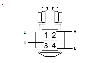
1. INSPECT REAR LIGHT ASSEMBLY LH
| (a) Apply battery voltage to the connector and check the light illumination condition. OK:
If the result is not as specified, replace the rear light assembly LH. |
|
2. INSPECT REAR LIGHT ASSEMBLY RH
| (a) Apply battery voltage to the connector and check the light illumination condition. OK:
If the result is not as specified, replace the rear light assembly RH. |
|
READ NEXT:
 Reassembly
REASSEMBLY CAUTION / NOTICE / HINT HINT:
Use the same procedure for the RH and LH sides.
The procedure listed below is for the LH side.
PROCEDURE 1. INSTALL REAR LIGHT SOCKET AND WIRE LH (a) A
Installation
INSTALLATION CAUTION / NOTICE / HINT HINT:
Use the same procedure for the RH and LH sides.
The procedure described below is for the LH side.
PROCEDURE 1. INSTALL REAR LIGHT ASSEMBLY LH (a)
SEE MORE:
Installation
INSTALLATION PROCEDURE 1. INSTALL AIR CONDITIONER PRESSURE SENSOR (a) Remove the vinyl tape from the liquid pipe sub-assembly and the connecting part of the air conditioner pressure sensor. (b) Apply sufficient compressor oil to the O-ring of a new air conditioner pressure sensor and the connecting
Installation
INSTALLATION CAUTION / NOTICE / HINT CAUTION: Wear protective gloves. Sharp areas on the parts may injure your hands. PROCEDURE 1. INSTALL SEAT HEATER CONTROL SUB-ASSEMBLY (for LH Side) (a) for Manual Seat: (1) Attach the hook. (2) Attach the clamp and install the seat heater contr
