- Short in CAN main bus wire
- Short in CAN branch wire
- Central gateway ECU (network gateway ECU)
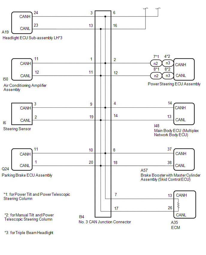
- ECM
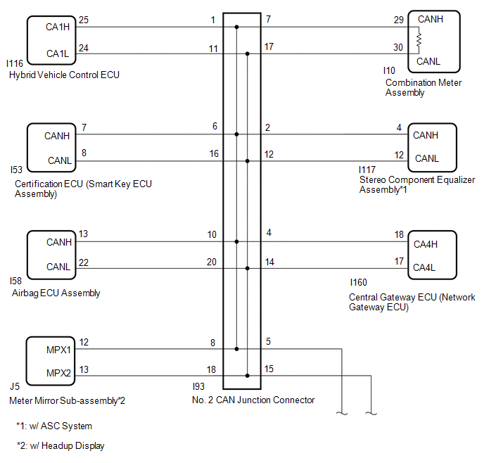
- Combination meter assembly
- Air conditioning amplifier assembly
- Power steering ECU assembly
- Certification ECU (smart key ECU assembly)
- Airbag ECU assembly
- Main body ECU (multiplex network body ECU)
- Brake booster with master cylinder assembly (skid control ECU)
- Steering sensor
- Parking brake ECU assembly
- Meter mirror sub-assembly*1
- Stereo component equalizer assembly*2
- Headlight ECU sub-assembly LH*3
- Hybrid vehicle control ECU
- No. 2 CAN junction connector
- No. 3 CAN junction connector
Lexus NX: Check Bus 2 Lines for Short Circuit
Lexus NX Service Manual / Power Source & Network / Networking / Can Communication System / Check Bus 2 Lines for Short Circuit
DESCRIPTION
There may be a short circuit between the CAN main bus wire and/or CAN branch wire when the resistance between terminals 18 (CA4H) and 17 (CA4L) of the central gateway ECU (network gateway ECU) is below 54 Ω.
| Symptom | Trouble Area |
|---|---|
|
*1: w/ Headup Display
*2: w/ ASC System *3: for Triple Beam Headlight | |
| Resistance between terminals 18 (CA4H) and 17 (CA4L) of central gateway ECU (network gateway ECU) is below 54 Ω. | |
WIRING DIAGRAM
CAUTION / NOTICE / HINT
CAUTION:
When performing the confirmation driving pattern, obey all speed limits and traffic laws.
NOTICE:
- Inspect the fuses for circuits related to this system before performing the following procedure.
- Before measuring the resistance of the CAN bus, turn the power switch off and leave the vehicle for 1 minute or more without operating the key or any switches, or opening or closing the doors. After that, disconnect the cable from the negative (-) auxiliary battery terminal and leave the vehicle for 1 minute or more before measuring the resistance.
-
After turning the power switch off, waiting time may be required before disconnecting the cable from the negative (-) auxiliary battery terminal.
Click here
.gif)
-
When disconnecting and reconnecting the auxiliary battery.
Click here
HINT:
When disconnecting and reconnecting the auxiliary battery, there is an automatic learning function that completes learning when the respective system is used.
Click here
-
Some parts must be initialized and set when replacing or removing and installing parts.
Click here
-
Because the order of diagnosis is important to allow correct diagnosis, make sure to begin troubleshooting using How to Proceed with Troubleshooting when CAN communication system related DTCs are output.
Click here
-
After performing repairs, perform the DTC check procedure and confirm that the DTCs are not output again.
DTC check procedure: Turn the power switch on (IG) and wait for 1 minute or more. Then operate the suspected malfunctioning system and drive the vehicle at 60 km/h (37 mph) or more for 5 minutes or more.
-
After the repair, perform the CAN bus check and check that all the ECUs and sensors connected to the CAN communication system are displayed as normal.
Click here
- When replacing the combination meter assembly, always replace it with a new one. If a combination meter assembly which was installed to another vehicle is used, the information stored in it will not match the information from the vehicle and a DTC may be stored.
HINT:
- Operating the power switch, any switches or any doors triggers related ECU and sensor communication with the CAN, which causes resistance variation.
- Even after DTCs are cleared, if a DTC is stored again after driving the vehicle for a while, the malfunction may be occurring due to vibration of the vehicle. In such a case, wiggling the ECUs or wire harness while performing the inspection below may help determine the cause of the malfunction.
PROCEDURE
| 1. | CHECK FOR SHORT IN CAN BUS WIRES (NO. 2 CAN JUNCTION CONNECTOR) |
(a) Disconnect the cable from the negative (-) auxiliary battery terminal.
(b) Disconnect the No. 2 CAN junction connector.
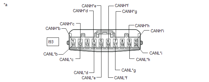
| *a | Front view of wire harness connector (to No. 2 CAN Junction Connector) | *b | to Hybrid Vehicle Control ECU |
| *c | to Stereo Component Equalizer Assembly (w/ ASC System) | *d | to Central Gateway ECU (Network Gateway ECU) |
| *e | to No. 3 CAN Junction Connector | *f | to Certification ECU (Smart Key ECU Assembly) |
| *g | to Combination Meter Assembly | *h | to Meter Mirror Sub-assembly (w/ Headup Display) |
| *i | to Airbag ECU Assembly | - | - |
(c) Measure the resistance according to the value(s) in the table below.
Standard Resistance:
| Tester Connection | Condition | Specified Condition | Connected to |
|---|---|---|---|
|
*1: w/ ASC System
*2: w/ Headup Display | |||
| I93-1 (CANH) - I93-11 (CANL) | Cable disconnected from negative (-) auxiliary battery terminal | 200 Ω or higher | Hybrid vehicle control ECU |
| I93-2 (CANH) - I93-12 (CANL) | Cable disconnected from negative (-) auxiliary battery terminal | 200 Ω or higher | Stereo component equalizer assembly*1 |
| I93-4 (CANH) - I93-14 (CANL) | Cable disconnected from negative (-) auxiliary battery terminal | 200 Ω or higher | Central gateway ECU (network gateway ECU) |
| I93-5 (CANH) - I93-15 (CANL) | Cable disconnected from negative (-) auxiliary battery terminal | 108 to 132 Ω | No. 3 CAN junction connector |
| I93-6 (CANH) - I93-16 (CANL) | Cable disconnected from negative (-) auxiliary battery terminal | 200 Ω or higher | Certification ECU (smart key ECU assembly) |
| I93-7 (CANH) - I93-17 (CANL) | Cable disconnected from negative (-) auxiliary battery terminal | 108 to 132 Ω | Combination meter assembly |
| I93-9 (CANH) - I93-19 (CANL) | Cable disconnected from negative (-) auxiliary battery terminal | 200 Ω or higher | Meter mirror sub-assembly*2 |
| I93-10 (CANH) - I93-20 (CANL) | Cable disconnected from negative (-) auxiliary battery terminal | 200 Ω or higher | Airbag ECU assembly |
| Result | Proceed to |
|---|---|
| OK | A |
| NG (Central gateway ECU [network gateway ECU] CAN branch wire) | B |
| NG (Combination meter assembly CAN main wire) | C |
| NG (No. 3 CAN junction connector CAN main wire) | D |
| NG (Wire to ECU or sensor) | E |
| A | .gif) | REPLACE NO. 2 CAN JUNCTION CONNECTOR |
| C | | GO TO STEP 4 |
| D | | GO TO STEP 6 |
| E | | GO TO STEP 10 |
|
.gif)
| 2. | CONNECT CONNECTOR |
(a) Reconnect the I93 No. 2 CAN junction connector.
|
| 3. | CHECK FOR SHORT IN CAN BUS WIRES (CENTRAL GATEWAY ECU [NETWORK GATEWAY ECU] - NO. 2 CAN JUNCTION CONNECTOR) |
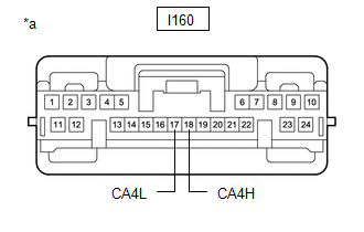
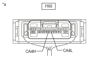
(a) Disconnect the central gateway ECU (network gateway ECU) connector.
| (b) Disconnect the No. 2 CAN junction connector. |
|
(c) Measure the resistance according to the value(s) in the table below.
Standard Resistance:
| Tester Connection | Condition | Specified Condition |
|---|---|---|
| I160-18 (CA4H) - I160-17 (CA4L) | Cable disconnected from negative (-) auxiliary battery terminal | 108 to 132 Ω |
| OK | | REPLACE CENTRAL GATEWAY ECU (NETWORK GATEWAY ECU) |
| NG | | REPAIR OR REPLACE CAN BRANCH WIRE OR CONNECTOR (CENTRAL GATEWAY ECU [NETWORK GATEWAY ECU] - NO. 2 CAN JUNCTION CONNECTOR) |
| 4. | CONNECT CONNECTOR |
(a) Reconnect the I93 No. 2 CAN junction connector.
|
| 5. | CHECK FOR SHORT IN CAN BUS WIRES (COMBINATION METER ASSEMBLY - NO. 2 CAN JUNCTION CONNECTOR) |
| (a) Disconnect the combination meter assembly connector. |
|
.png)
(b) Measure the resistance according to the value(s) in the table below.
Standard Resistance:
| Tester Connection | Condition | Specified Condition |
|---|---|---|
| I10-29 (CANH) - I10-30 (CANL) | Cable disconnected from negative (-) auxiliary battery terminal | 108 to 132 Ω |
| OK | | REPLACE COMBINATION METER ASSEMBLY |
| NG | | REPAIR OR REPLACE CAN MAIN WIRE OR CONNECTOR (COMBINATION METER ASSEMBLY - NO. 2 CAN JUNCTION CONNECTOR) |
| 6. | CONNECT CONNECTOR |
(a) Reconnect the I93 No. 2 CAN junction connector.
|
| 7. | CHECK FOR SHORT IN CAN BUS WIRES (NO. 3 CAN JUNCTION CONNECTOR) |
(a) Disconnect the No. 3 CAN junction connector.
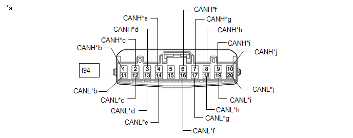
| *a | Front view of wire harness connector (to No. 3 CAN Junction Connector) | *b | to Air Conditioning Amplifier Assembly |
| *c | to Power Steering ECU Assembly | *d | to Headlight ECU Sub-assembly LH (for Triple Beam Headlight) |
| *e | to Main Body ECU (Multiplex Network Gateway ECU) | *f | to No. 2 CAN Junction Connector |
| *g | to ECM | *h | to Brake Booster with Master Cylinder Assembly (Skid Control ECU) |
| *i | to Steering Sensor | *j | to Parking Brake ECU Assembly |
(b) Measure the resistance according to the value(s) in the table below.
Standard Resistance:
| Tester Connection | Condition | Specified Condition | Connected to |
|---|---|---|---|
| *: for Triple Beam Headlight | |||
| I94-1 (CANH) - I94-11 (CANL) | Cable disconnected from negative (-) auxiliary battery terminal | 200 Ω or higher | Air conditioning amplifier assembly |
| I94-2 (CANH) - I94-12 (CANL) | Cable disconnected from negative (-) auxiliary battery terminal | 200 Ω or higher | Power steering ECU assembly |
| I94-3 (CANH) - I94-13 (CANL) | Cable disconnected from negative (-) auxiliary battery terminal | 200 Ω or higher | Headlight ECU sub-assembly LH* |
| I94-4 (CANH) - I94-14 (CANL) | Cable disconnected from negative (-) auxiliary battery terminal | 200 Ω or higher | Main body ECU (multiplex network gateway ECU) |
| I94-6 (CANH) - I94-16 (CANL) | Cable disconnected from negative (-) auxiliary battery terminal | 108 to 132 Ω | No. 2 CAN junction connector |
| I94-7 (CANH) - I94-17 (CANL) | Cable disconnected from negative (-) auxiliary battery terminal | 108 to 132 Ω | ECM |
| I94-8 (CANH) - I94-18 (CANL) | Cable disconnected from negative (-) auxiliary battery terminal | 200 Ω or higher | Brake booster with master cylinder assembly (skid control ECU) |
| I94-9 (CANH) - I94-19 (CANL) | Cable disconnected from negative (-) auxiliary battery terminal | 200 Ω or higher | Steering sensor |
| I94-10 (CANH) - I94-20 (CANL) | Cable disconnected from negative (-) auxiliary battery terminal | 200 Ω or higher | Parking brake ECU assembly |
| Result | Proceed to |
|---|---|
| OK | A |
| NG (ECM CAN main wire) | B |
| NG (No. 2 CAN junction connector CAN main wire) | C |
| NG (Wire to ECU or sensor) | D |
| A | | REPLACE NO. 3 CAN JUNCTION CONNECTOR |
| C | | REPAIR OR REPLACE CAN MAIN WIRE OR CONNECTOR (NO. 3 CAN JUNCTION CONNECTOR - NO. 2 CAN JUNCTION CONNECTOR) |
| D | | GO TO STEP 10 |
|
| 8. | CONNECT CONNECTOR |
(a) Reconnect the I94 No. 3 CAN junction connector.
|
| 9. | CHECK FOR SHORT IN CAN BUS WIRES (ECM - NO. 3 CAN JUNCTION CONNECTOR) |
| (a) Disconnect the ECM connector. |
|
.png)
(b) Measure the resistance according to the value(s) in the table below.
Standard Resistance:
| Tester Connection | Condition | Specified Condition |
|---|---|---|
| A35-13 (CANH) - A35-26 (CANL) | Cable disconnected from negative (-) auxiliary battery terminal | 108 to 132 Ω |
| OK | | REPLACE ECM |
| NG | | REPAIR OR REPLACE CAN MAIN WIRE OR CONNECTOR (ECM - NO. 3 CAN JUNCTION CONNECTOR) |
| 10. | CHECK FOR SHORT IN CAN BUS WIRES (ECU, SENSOR) |
(a) Reconnect all wire harness connectors.
(b) Disconnect the connector that includes terminals CANH and CANL from the ECU or sensor to which the short circuited branch line is connected.
Click here
| (c) Measure the resistance according to the value(s) in the table below. Standard Resistance:
HINT: If the resistance becomes normal (between 54 and 69 Ω) when the connector is disconnected from the ECU or sensor, there may be a short in the ECU or sensor. |
|
| OK | | REPLACE ECU OR SENSOR |
| NG | | REPAIR OR REPLACE HARNESS OR CONNECTOR |
READ NEXT:
 Check Bus 2 Line for Short to +B
DESCRIPTION There may be a short circuit between one of the CAN bus wire and +B when there is no resistance between terminal 18 (CA4H) of the central gateway ECU (network gateway ECU) and terminal 16
Check Bus 2 Line for Short to GND
DESCRIPTION There may be a short circuit between one of the CAN bus wire and GND when there is no resistance between terminal 18 (CA4H) of the central gateway ECU (network gateway ECU) and terminal 4
Open in One Side of Bus 2 Branch Line
DESCRIPTION When the CAN bus main lines are normal (no open, short to ground, short to +B or short between lines) and there is an ECU or sensor on the "Communication Bus Check" screen that is indicate
SEE MORE:
Installation
INSTALLATION CAUTION / NOTICE / HINT NOTICE:
When replacing the windshield glass of a vehicle equipped with a forward recognition camera, make sure to use a Lexus genuine part. If a non-Lexus genuine part is used, the forward recognition camera may not be able to be installed due to a missing bra
Hybrid Battery Voltage System Isolation Fault (P0AA6-526,P0AA6-611,P0AA6-612,P0AA6-613,P0AA6-614,P0AA6-655)
DESCRIPTION The hybrid vehicle control ECU monitors the battery voltage sensor and detects insulation malfunctions in the high-voltage system. DTC No. Detection Item DTC Detection Condition Trouble Area MIL Warning Indicate P0AA6-526 Hybrid Battery Voltage System Isolation Fault
© 2016-2026 Copyright www.lexunx.com
