.gif)
- Power switch on (IG)
- Climate control switch (for Driver Side) on
Lexus NX: Climate Control System does not Operate on Driver Side
Lexus NX Service Manual / Vehicle Interior / Seat / Climate Control Seat System / Climate Control System does not Operate on Driver Side
DESCRIPTION
The air conditioning control assembly sends operation signals to the air conditioning amplifier assembly via the LIN communication line. The air conditioning amplifier assembly actives the seat blowers according these signals.
WIRING DIAGRAM
.png)
CAUTION / NOTICE / HINT
NOTICE:
- The climate control seat system uses the LIN communication system. Inspect the communication function by following How to Proceed with Troubleshooting. Troubleshoot the climate control seat system after confirming that the communication systems are functioning properly.
-
If the auxiliary battery voltage is low, the climate control seat system may not operate. When "High Power Consumption / Partial Limit On AC/Heater Operation" is displayed on the multi-information display in the combination meter assembly, inspect the auxiliary battery, referring to On-vehicle Inspection for the charging system.
Click here
.gif)
HINT:
If the auxiliary battery voltage is low, "Operation Limitation Control History Count (Level 1)" and "Operation Limitation Control History Count (Level 2) is counted.
Click here
-
If the auxiliary battery voltage is low, the climate control seat system may not operate. Refer to Data List for the power steering system.
for Manual Tilt and Manual Telescopic Steering Column: Click here
for Power Tilt and Power Telescopic Steering Column: Click here
- Inspect the fuses for circuits related to this system before performing the following procedure.
- When the auxiliary battery is disconnected or the air conditioning amplifier assembly is replaced, be sure to perform servo motor initialization.
PROCEDURE
| 1. | CHECK CLIMATE CONTROL SEAT OPERATION (for Driver Side) |
(a) Check the climate control seat operation.
Click here
| Result | Proceed to |
|---|---|
| Only seat cushion climate control blower assembly LH does not operate | A |
| Only seatback climate control blower LH does not operate | B |
| Both climate control blowers do not operate | C |
| A | .gif) | REPLACE SEAT CUSHION CLIMATE CONTROL BLOWER ASSEMBLY LH |
| C | | GO TO STEP 4 |
|
| 2. | CHECK HARNESS AND CONNECTOR (SEAT CUSHION CLIMATE CONTROL BLOWER ASSEMBLY LH - SEATBACK CLIMATE CONTROL BLOWER LH) |
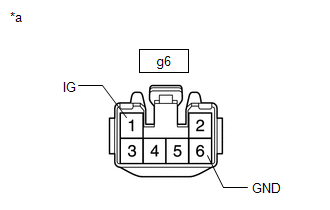
(a) Disconnect the g6 seat cushion climate control blower assembly LH connector.
(b) Disconnect the k1 seatback climate control blower LH connector.
(c) Measure the resistance according to the value(s) in the table below.
Standard Resistance:
| Tester Connection | Condition | Specified Condition |
|---|---|---|
| g6-2 (GND2) - k1-3 (GND) | Always | Below 1 Ω |
| g6-2 (GND2) or k1-3 (GND) - Body ground | Always | 10 kΩ or higher |
| g6-3 (IGB) - k1-1 (IGB) | Always | Below 1 Ω |
| g6-3 (IGB) or k1-1 (IGB) - Body ground | Always | 10 kΩ or higher |
| g6-4 (VS) - k1-2 (VS) | Always | Below 1 Ω |
| g6-4 (VS) or k1-2 (VS) - Body ground | Always | 10 kΩ or higher |
| NG | | REPAIR OR REPLACE HARNESS OR CONNECTOR |
|
| 3. | CHECK SEATBACK CLIMATE CONTROL BLOWER LH |
(a) Temporarily replace the seatback climate control blower LH with a new or normally functioning one.
Click here
(b) Check the climate control seat operation.
Click here
| OK | | END (SEATBACK CLIMATE CONTROL BLOWER LH WAS DEFECTIVE) |
| NG | | REPLACE SEAT CUSHION CLIMATE CONTROL BLOWER ASSEMBLY LH |
| 4. | CHECK HARNESS AND CONNECTOR (SEAT CUSHION CLIMATE CONTROL BLOWER ASSEMBLY LH - BATTERY AND BODY GROUND) |
| (a) Disconnect the seat cushion climate control blower assembly LH connector. |
|
(b) Measure the voltage according to the value(s) in the table below.
Standard Voltage:
| Tester Connection | Switch Condition | Specified Condition |
|---|---|---|
| g6-1 (IG) - Body ground | Power switch on (IG) | 11 to 14 V |
| Power switch off | Below 1 V |
(c) Measure the resistance according to the value(s) in the table below.
Standard Resistance:
| Tester Connection | Condition | Specified Condition |
|---|---|---|
| g6-6 (GND) - Body ground | Always | Below 1 Ω |
| NG | | REPAIR OR REPLACE HARNESS OR CONNECTOR |
|
| 5. | CHECK HARNESS AND CONNECTOR (AIR CONDITIONING AMPLIFIER ASSEMBLY - SEAT CUSHION CLIMATE CONTROL BLOWER ASSEMBLY LH) |
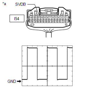
(a) Disconnect the I54 air conditioning amplifier assembly connector.
(b) Disconnect the g6 seat cushion climate control blower assembly LH connector.
(c) Measure the resistance according to the value(s) in the table below.
Standard Resistance:
| Tester Connection | Condition | Specified Condition |
|---|---|---|
| I54-11 (SVDB) - g6-5 (SI) | Always | Below 1 Ω |
| I54-11 (SVDB) or g6-5 (SI) - Body ground | Always | 10 kΩ or higher |
| NG | | REPAIR OR REPLACE HARNESS OR CONNECTOR |
|
| 6. | CHECK AIR CONDITIONING AMPLIFIER ASSEMBLY |
| (a) Reconnect the air conditioning amplifier assembly connector. |
|
(b) Reconnect the g6 seat cushion climate control blower assembly LH connector.
(c) Check for pulses according to the condition(s) in the table below.
Measurement Condition| Item | Content |
|---|---|
| Tester Connection | I54-11 (SVDB) - Body ground |
| Tool Setting | 1 V/DIV., 1 ms/DIV. |
| Vehicle Condition | |
OK:
Waveform is similar to that shown in the illustration.
| OK | | REPLACE SEAT CUSHION CLIMATE CONTROL BLOWER ASSEMBLY LH |
|
| 7. | CHECK AIR CONDITIONING AMPLIFIER ASSEMBLY |
(a) Temporarily replace the air conditioning amplifier assembly with a new or normally functioning one.
Click here
(b) Check the climate control seat operation.
Click here
OK:
Climate control seat system is operated normally.
| OK | | END (AIR CONDITIONING AMPLIFIER ASSEMBLY WAS DEFECTIVE) |
| NG | | REPLACE AIR CONDITIONING CONTROL ASSEMBLY |
READ NEXT:
 Climate Control System does not Operate on Passenger Side
DESCRIPTION The air conditioning control assembly sends operation signals to the air conditioning amplifier assembly via the LIN communication line. The air conditioning amplifier assembly actives the
Parts Location
PARTS LOCATION ILLUSTRATION *1 FRONT SEAT INNER BELT ASSEMBLY LH *2 FRONT SEAT OUTER BELT ASSEMBLY LH *3 OUTER MIRROR CONTROL ECU ASSEMBLY (for Driver Side) *4 NO. 2 ENGINE ROOM RE
SEE MORE:
DC / DC Converter Temperature Sensor "B" Range / Performance (P0C3E-628,P0C41-627)
DTC SUMMARY MALFUNCTION DESCRIPTION These DTCs indicate the boost converter temperature sensor (lower) value is abnormal. The cause of this malfunction may be one of the following: Internal inverter malfunction
Inverter with converter assembly internal circuit malfunction
Hybrid cooling syste
Internal Control Module Software Incompatibility Not Programmed (U030051,U030057)
DESCRIPTION
The forward recognition camera receives vehicle information (Conv/HV) from the hybrid vehicle control ECU via the CAN communication line.
When the forward recognition camera is unable to determine the vehicle information (Conv/HV) from the vehicle information (Conv/HV) sent from the
© 2016-2026 Copyright www.lexunx.com
