Lexus NX: Installation
INSTALLATION
CAUTION / NOTICE / HINT
HINT:
- Use the same procedure for the RH and LH sides.
- The procedure listed below is for the LH side.
PROCEDURE
1. INSTALL REAR NO. 1 SPRING BUMPER LH
| (a) Using SST, install the rear No. 1 spring bumper LH. SST: 09922-10010 Torque: Specified tightening torque : 30 N·m {306 kgf·cm, 22 ft·lbf} HINT:
|
|
2. TEMPORARILY INSTALL REAR NO. 2 SUSPENSION ARM ASSEMBLY LH
(a) Temporarily install the rear No. 2 suspension arm to the suspension member with the bolt and nut.
NOTICE:
Since a stopper nut is used, tighten the bolt.
HINT:
Insert the bolt from the rear of the vehicle.
3. INSTALL REAR UPPER COIL SPRING INSULATOR LH
Click here .gif)
4. INSTALL REAR LOWER COIL SPRING INSULATOR LH
Click here
5. INSTALL REAR COIL SPRING LH
Click here
6. INSTALL REAR STABILIZER LINK ASSEMBLY LH
Click here
7. TEMPORARILY INSTALL REAR NO. 1 SUSPENSION ARM ASSEMBLY LH
| (a) Temporarily install the rear No. 1 suspension arm to the rear axle carrier with a new nut. |
|
.png)
| (b) Insert the rear suspension toe adjust cam sub-assembly from the rear of the vehicle to install the rear No. 1 suspension arm assembly LH, and then temporarily install the No. 2 camber adjust cam with the nut. |
|
.png)
8. TEMPORARILY INSTALL REAR SHOCK ABSORBER ASSEMBLY LH
Click here
9. STABILIZE SUSPENSION
Click here
10. TIGHTEN REAR NO. 2 SUSPENSION ARM ASSEMBLY LH
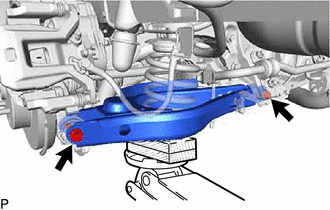
(a) Tighten the 2 bolts and nut of the rear No. 2 suspension arm assembly.
Torque:
90 N·m {918 kgf·cm, 66 ft·lbf}
NOTICE:
Since a stopper nut is used, tighten the bolt.
11. TIGHTEN REAR SHOCK ABSORBER ASSEMBLY LH
Click here
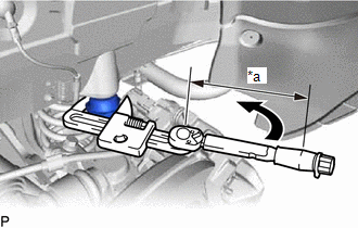
12. TIGHTEN REAR NO. 1 SUSPENSION ARM ASSEMBLY LH
| (a) Tighten the nut. Torque: 100 N·m {1020 kgf·cm, 74 ft·lbf} |
|
| (b) Tighten the nut of the rear No. 1 suspension arm. Torque: 120 N·m {1224 kgf·cm, 89 ft·lbf} NOTICE: Align the matchmarks on the rear suspension member and adjust cam. |
|
13. INSTALL REAR HEIGHT CONTROL SENSOR SUB-ASSEMBLY LH
Click here
14. INSTALL REAR SUSPENSION ARM COVER LH
| (a) Insert the 2 claws of the rear suspension arm cover LH into the rear No. 2 suspension arm assembly LH. |
|
.png)
(b) Install the rear suspension arm cover LH with the 2 bolts.
Torque:
12 N·m {122 kgf·cm, 9 ft·lbf}
NOTICE:
Make sure that the 2 claws of the rear suspension arm cover are inserted.
15. INSTALL REAR WHEEL
Click here
16. INSPECT AND ADJUST REAR WHEEL ALIGNMENT
Click here
17. HEIGHT CONTROL SENSOR SIGNAL INITIALIZATION
Click here
18. PERFORM INITIALIZATION
Click here
READ NEXT:
 Components
COMPONENTS ILLUSTRATION *A w/o AVS - - *1 REAR NO. 1 SHOCK ABSORBER BRACKET LH *2 REAR SHOCK ABSORBER ASSEMBLY LH *3 REAR SUSPENSION ARM COVER LH - N*m (kgf*c
Removal
REMOVAL CAUTION / NOTICE / HINT HINT:
Use the same procedure for the RH and LH sides.
The procedure listed below is for the LH side.
PROCEDURE 1. REMOVE REAR WHEEL Click here 2. DISCONNECT R
SEE MORE:
Precaution
PRECAUTION PRECAUTION FOR DISCONNECTING CABLE FROM NEGATIVE AUXILIARY BATTERY TERMINAL NOTICE: When disconnecting and reconnecting the auxiliary battery. Click here HINT: When disconnecting and reconnecting the auxiliary battery, there is an automatic learning function that completes learning when
Entry Exterior Alarm and Answer-back Buzzer do not Sound
DESCRIPTION The smart access system with push-button start (for Entry Function) uses the wireless door lock buzzer to perform various vehicle exterior warnings. When the conditions of each warning are met, the certification ECU (smart key ECU assembly) sends a buzzer activation request signal to the
