Lexus NX: Components
COMPONENTS
ILLUSTRATION
.png)
| *1 | DECK FLOOR BOX LH | *2 | NO. 3 DECK BOARD SUB-ASSEMBLY |
| *3 | REAR DECK FLOOR BOX | *4 | NEGATIVE AUXILIARY BATTERY TERMINAL |
.png) | N*m (kgf*cm, ft.*lbf): Specified torque | - | - |
ILLUSTRATION
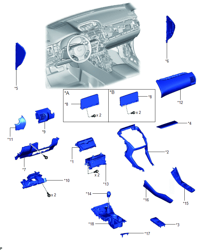
| *A | for 8 Inch | *B | for 10.3 Inch |
| *1 | AIR CONDITIONING CONTROL ASSEMBLY | *2 | CENTER INSTRUMENT CLUSTER FINISH PANEL ASSEMBLY |
| *3 | CONSOLE ARMREST ASSEMBLY | *4 | INSTRUMENT PANEL FINISH PLATE |
| *5 | INSTRUMENT SIDE PANEL LH | *6 | INSTRUMENT SIDE PANEL RH |
| *7 | LOWER NO. 1 INSTRUMENT PANEL FINISH PANEL | *8 | MULTI-DISPLAY ASSEMBLY WITH BRACKET |
| *9 | NO. 1 INSTRUMENT PANEL SAFETY PAD SUB-ASSEMBLY | *10 | NO. 1 INSTRUMENT PANEL UNDER COVER SUB-ASSEMBLY |
| *11 | NO. 1 SWITCH HOLE BASE | *12 | NO. 2 INSTRUMENT PANEL SAFETY PAD SUB-ASSEMBLY |
| *13 | RADIO RECEIVER ASSEMBLY WITH BRACKET | *14 | SHIFT LEVER KNOB SUB-ASSEMBLY |
| *15 | UPPER NO. 1 CONSOLE PANEL GARNISH | *16 | UPPER NO. 2 CONSOLE PANEL GARNISH |
| *17 | UPPER REAR CONSOLE PANEL | *18 | UPPER REAR CONSOLE PANEL SUB-ASSEMBLY |
ILLUSTRATION
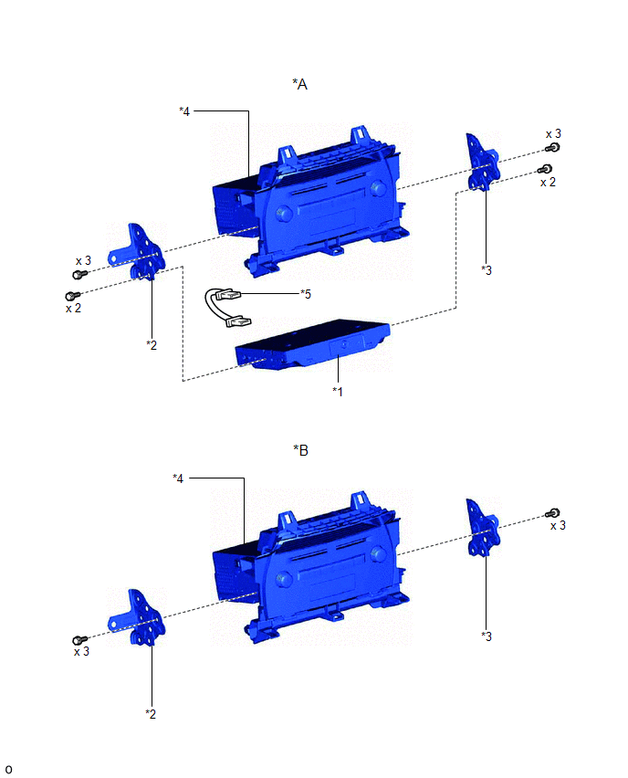
| *A | w/ Navigation System | *B | w/o Navigation System |
| *1 | NAVIGATION ECU | *2 | NO. 1 RADIO BRACKET |
| *3 | NO. 2 RADIO BRACKET | *4 | RADIO RECEIVER ASSEMBLY |
| *5 | NAVIGATION WIRE | - | - |
READ NEXT:
 Removal
REMOVAL PROCEDURE 1. REMOVE DECK BOARD ASSEMBLY Click here 2. REMOVE NO. 3 DECK BOARD SUB-ASSEMBLY Click here 3. REMOVE REAR DECK FLOOR BOX Click here 4. REMOVE DECK FLOOR BOX LH Click here 5.
Installation
INSTALLATION PROCEDURE 1. INSTALL RADIO RECEIVER ASSEMBLY 2. INSTALL NAVIGATION ECU Click here 3. INSTALL NO. 1 RADIO BRACKET (a) w/ Navigation System (1) Install the No. 1 radio bracket with the 5
SEE MORE:
Detecting Vehicle Submersion (B2277)
DESCRIPTION This DTC is stored when a malfunction in the water submersion detection circuit in the certification ECU (smart key ECU assembly) is detected. DTC No. Detection Item DTC Detection Condition Trouble Area Note B2277 Detecting Vehicle Submersion The water submersion detec
Master Reservoir Level Malfunction (C1202)
DESCRIPTION When a fluid level drop in the brake master cylinder reservoir assembly is detected, a signal is sent to the skid control ECU (brake booster with master cylinder assembly). If a DTC for the fluid level drop is stored, the warning will be canceled and the DTC will be cleared when the flui
