Lexus NX: Removal
REMOVAL
PROCEDURE
1. REMOVE DECK BOARD ASSEMBLY
Click here .gif)
2. REMOVE NO. 3 DECK BOARD SUB-ASSEMBLY
Click here
3. REMOVE REAR DECK FLOOR BOX
Click here
4. REMOVE DECK FLOOR BOX LH
Click here
5. PRECAUTION
CAUTION:
Be sure to read Precaution thoroughly before serving.
Click here
NOTICE:
After turning the power switch off, there may be a waiting time before disconnecting the negative (-) auxiliary battery terminal.
Click here
6. DISCONNECT CABLE FROM NEGATIVE AUXILIARY BATTERY TERMINAL
CAUTION:
- Wait at least 90 seconds after disconnecting the cable from the negative (-) auxiliary battery terminal to disable the SRS system.
- If the airbag deploys for any reason. it may cause a serious accident.
7. REMOVE INSTRUMENT PANEL FINISH PLATE
Click here
8. REMOVE MULTI-DISPLAY ASSEMBLY WITH BRACKET
Click here
9. REMOVE CONSOLE ARMREST ASSEMBLY
Click here
10. REMOVE UPPER REAR CONSOLE PANEL
Click here
11. REMOVE UPPER NO. 1 CONSOLE PANEL GARNISH
Click here
12. REMOVE UPPER NO. 2 CONSOLE PANEL GARNISH
Click here
13. REMOVE INSTRUMENT SIDE PANEL RH
Click here
14. REMOVE INSTRUMENT SIDE PANEL LH
Click here
15. REMOVE NO. 1 INSTRUMENT PANEL SAFETY PAD SUB-ASSEMBLY
Click here
16. REMOVE NO. 1 INSTRUMENT PANEL UNDER COVER SUB-ASSEMBLY
Click here
17. REMOVE LOWER NO. 1 INSTRUMENT PANEL FINISH PANEL
Click here
18. REMOVE NO. 1 SWITCH HOLE BASE
Click here
19. REMOVE NO. 2 INSTRUMENT PANEL SAFETY PAD SUB-ASSEMBLY
Click here
20. REMOVE CENTER INSTRUMENT CLUSTER FINISH PANEL ASSEMBLY
Click here
21. REMOVE SHIFT LEVER KNOB SUB-ASSEMBLY
Click here
22. REMOVE UPPER REAR CONSOLE PANEL SUB-ASSEMBLY
Click here
23. REMOVE AIR CONDITIONING CONTROL ASSEMBLY
Click here
24. REMOVE RADIO RECEIVER ASSEMBLY WITH BRACKET
| (a) Remove the 2 bolts. |
|
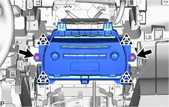
(b) Pull the radio receiver assembly with bracket toward the rear of the vehicle and disengage the 4 clips.
(c) Disconnect each connector and remove the radio receiver assembly with bracket.
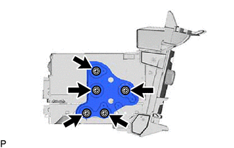
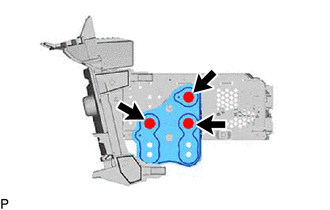
25. REMOVE NO. 1 RADIO BRACKET
| (a) w/ Navigation System (1) Remove the 5 screws and No. 1 radio bracket. |
|
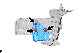
| (b) w/o Navigation System (1) Remove the 3 screws and No. 1 radio bracket. |
|
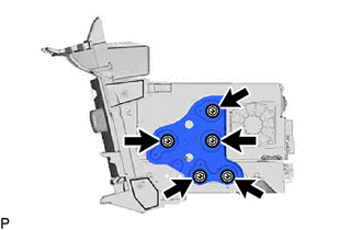
26. REMOVE NO. 2 RADIO BRACKET
| (a) w/ Navigation System (1) Remove the 5 screws and No. 2 radio bracket. |
|
| (b) w/ Navigation System (1) Remove the 3 screws and No. 2 radio bracket. |
|
27. REMOVE NAVIGATION ECU
Click here
28. REMOVE RADIO RECEIVER ASSEMBLY
READ NEXT:
 Installation
INSTALLATION PROCEDURE 1. INSTALL RADIO RECEIVER ASSEMBLY 2. INSTALL NAVIGATION ECU Click here 3. INSTALL NO. 1 RADIO BRACKET (a) w/ Navigation System (1) Install the No. 1 radio bracket with the 5
Components
COMPONENTS ILLUSTRATION *A for 8 Speakers *B for 10 Speakers *C for 14 Speakers - - *1 REAR DOOR INSIDE HANDLE BEZEL PLUG LH *2 REAR DOOR TRIM BOARD SUB-ASSEMBLY LH *
SEE MORE:
Accumulator Low Pressure (C1256)
DESCRIPTION The accumulator pressure sensor is built into the brake actuator (brake booster with master cylinder assembly) and detects the accumulator pressure. The skid control ECU (brake booster with master cylinder assembly) turns on the brake warning light / red (malfunction) and brake warning l
Check Bus 2 Line for Short to GND
DESCRIPTION There may be a short circuit between one of the CAN bus wire and GND when there is no resistance between terminal 18 (CA4H) of the central gateway ECU (network gateway ECU) and terminal 4 (CG) of the DLC3, or terminal 17 (CA4L) of the central gateway ECU (network gateway ECU) and termina
